This thread has been locked.

If you have a related question, please click the "Ask a related question" button in the top right corner. The newly created question will be automatically linked to this question.

LM5022: Simulation, hardware & system design tools forum

Part Number: LM5022
Other Parts Discussed in Thread: PMP10703

HI,

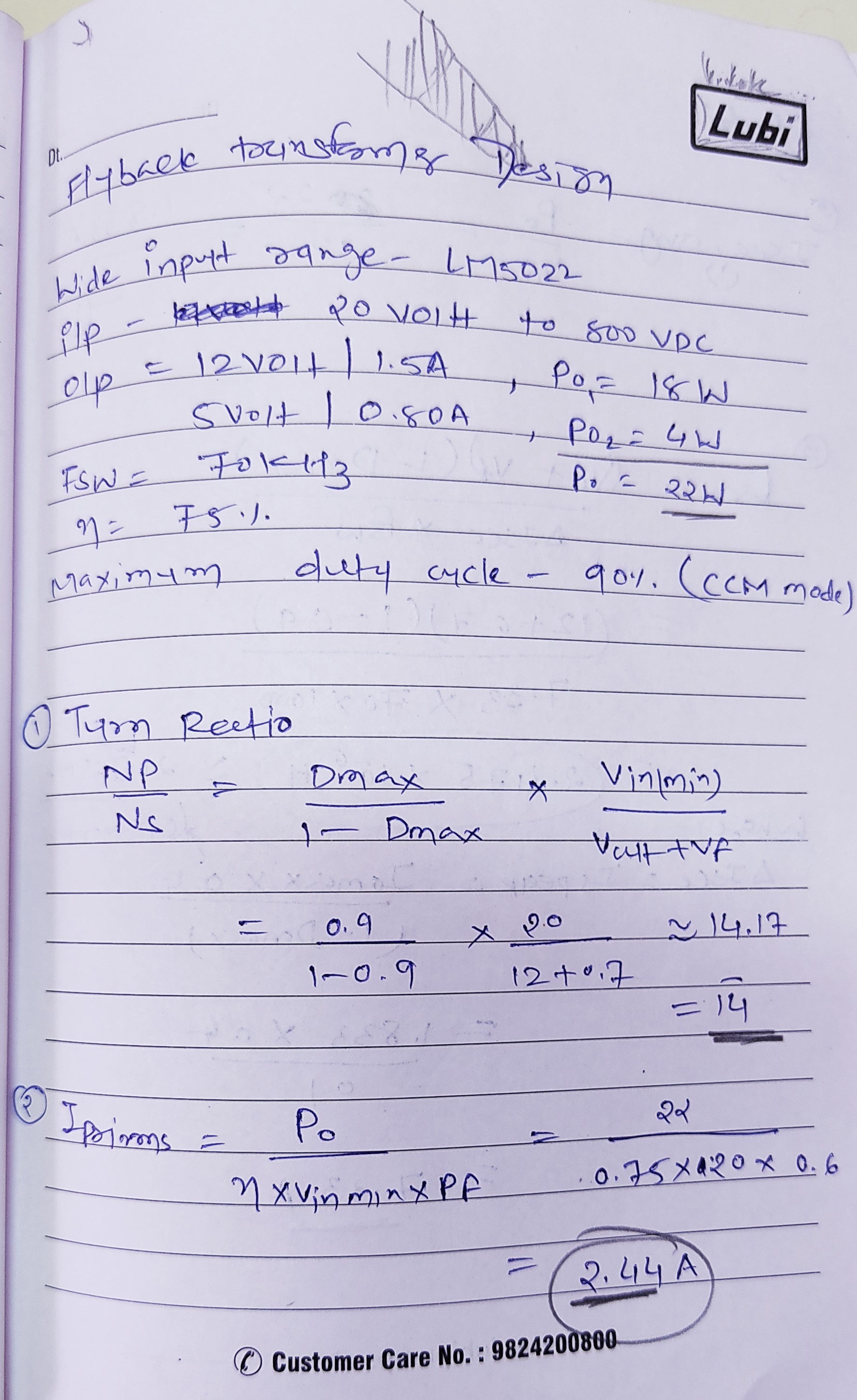
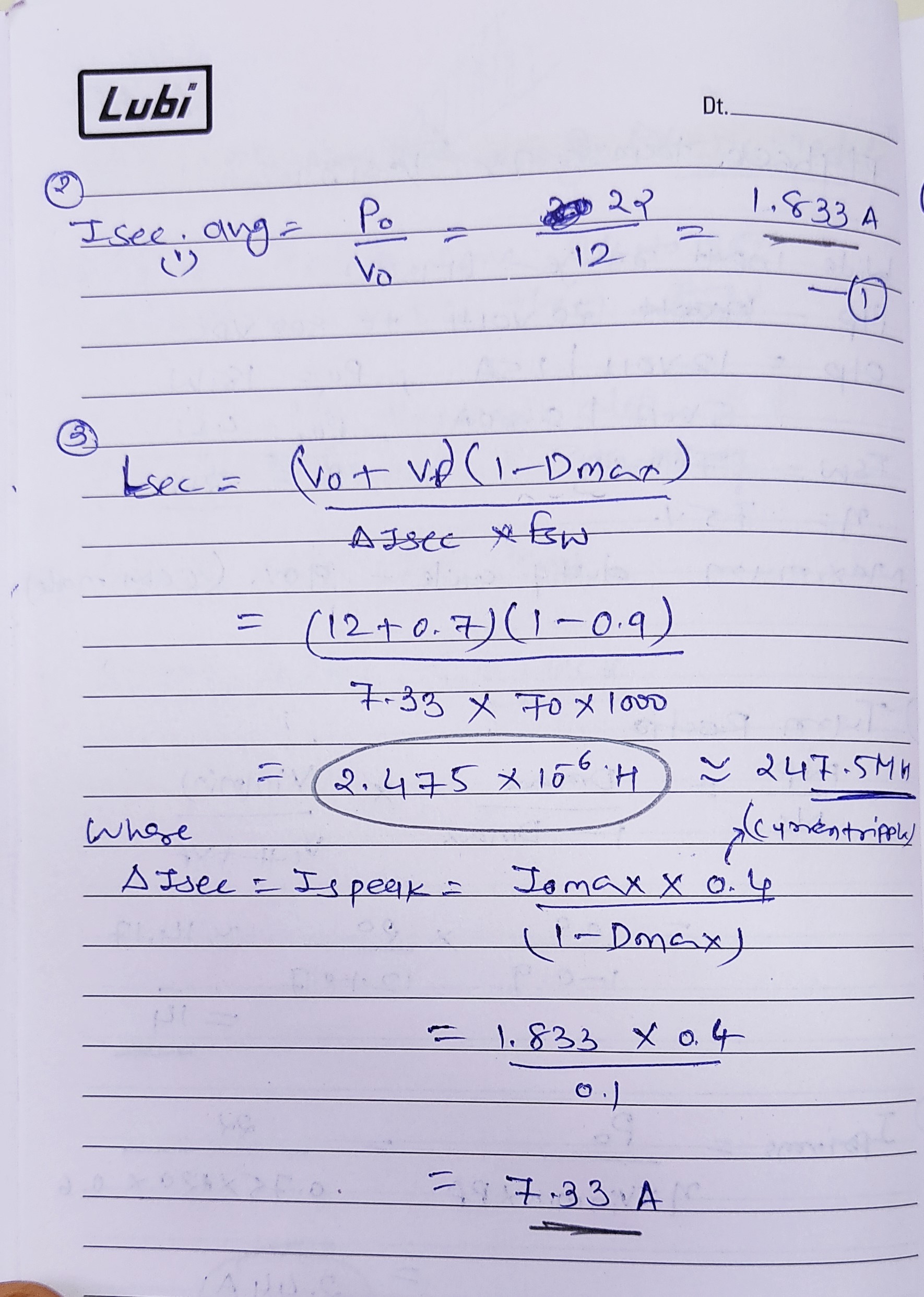
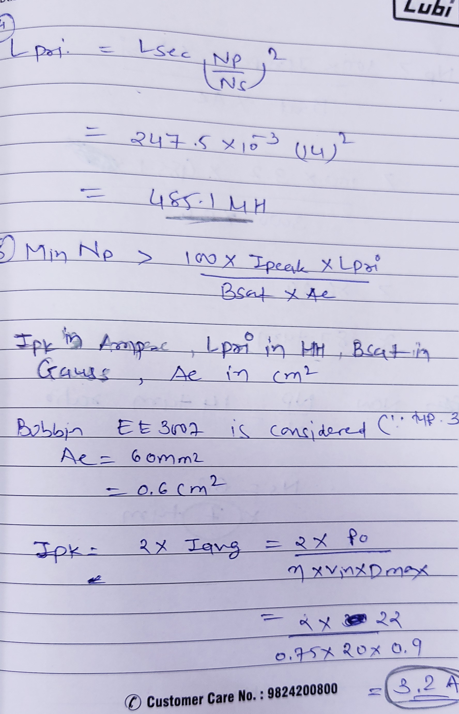
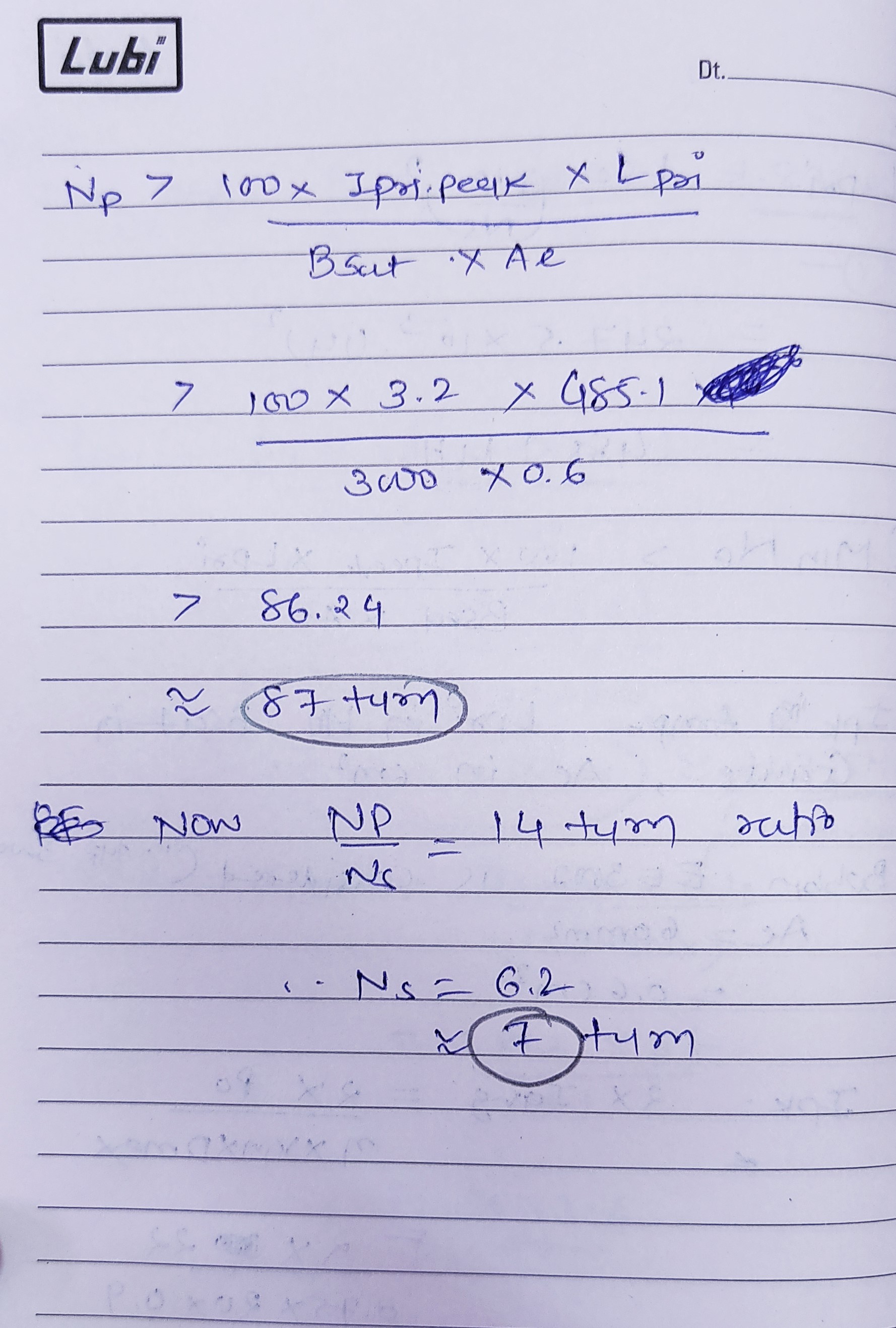
Kindly verify the transformer design for this wide input power supply using LM5022

i am designing the power supply for my solar inverter in which output of solar panel (750Vdc to 800Vdc) directly fed to the flyback power supply by using PMP7760 circuit.

i/p : 20v to 800V 

o/p : 12V/ 1.5A & 5 V / 800mA

Fsw: 70kHz

efficiency :  75max. duty Cycle: 90% in CCM Mode

i wanted to get 2 secondary ouput in which Sec_1 : 12 Volt/1.5A & Sec_2: 5 Volt/800 mA. 

Currently I've calculated the transformer turn, inductance and all with respect to 12 Volt/1.5 A.and for 5 volt/800mA  is remaining.

will anybody please verify it give me there valuable feedback on it.

i will follow the PMP7760 exact circuit for the same so that you can consider it respectively.

also suggest me that can i use multiple tapping for generate more supply voltage on secondary side ? 


Regards,

  • Hello Vivek,

    Please give us some time to review your design. We will answer in the next days.

  • Sure Brigitte,

    Thanks for Your response.

    i am looking at your more versatile product segment as well. I am waiting for the confirmation of my design.

    Also i wanted to Generate negative supply for my 4 gate driver ST_STGAP1AS_Automotive galvanically isolated advanced single gate driver : 

    - 10volt / 100 mA & 15volt /100mA. 

    all can be done in PMP7760 circuit or i have to make another individual supply for that?

    Regards, 

    Vivek Nirmal

  • Hi Vivek,

    Thank you for your patience. I'll look into your calculation.

    How many output do you want to have in total?

    Generally yes, you can add another winding turns on the secondary side for additional output. But make sure you check the transformer specs to see  how much galvanic isolation it provides between the turns.

    Thanks,

    Yinsong

  • Dear ,

    Thanks For your response.

    I need following output requirement,

    1.)  12volt /1.5 A

    2.) 15 Volt / 150mA 4Nos.

    3.) -10 Volt / 150mA 4 Nos.

    can it be possible or i should add one more converter circuit from 12Volt/1.5A input to generate 15 Volt and  -10volt.??

    and if it is possible what change needed in calculation as well.


    Thanks,


  • Hi Vivek,

    Thank you for the information.

    Yes. Since it uses the primary side regulation already, you can just add those outputs on the secondary side. The calculation will be the same because the negative output will just be a swap of the terminals and the diode direction. The power remains the same.

    Thanks,

    Yinsong

  • Dear  Yinsong Cai1, 

    if i just add those output on secondary side then should i change the transformer or not ? 

    You dint tell me about the calculation ?

    i am attaching you the transformer datasheet that i am going to use.is it ok?

    Also this transformer has Core area is 53.9mm2, Flux Density is 4800G @ 10Khz, 25°C; 3800G at 100°C. comfirmed with vendor as well.

    please comment on my calculation and transformer selection and give your valuable advise.

    GCI new updated R4 30W transformer G094215LF r 4.pdf

  • Hi Vivek,

    The transformer only has one secondary turns so you will need a transformer with more secondary turns. Since you have selected the primary aux turns ratio, the secondary side turns number will be decide accordingly. However, since the three outputs are all different, you may want to go back and make sure the turns ratio of the new transformer is good for all.

    For the calculation, you just need to add the additional part of the power into the total power and remember to reflect it to the primary side.

    Thanks,

    Yinsong

  • Dear Yinsong Cai1, 2

    From your reply it sounds like my calculation is correct for single output and also you've got better idea about my requirement as well.

    however, i need multiple output will you please provide the calculation for transformer or transformer part number so that i can buy it ?

    or do you have such kind of circuit with transformer so that i can use it for my project.

    give me your valuable advise.

    Regards,

  • Hi Vivek,

    Sorry but we do not recommend other components with specific manufacturers. That being said, the basic requirement would just be two primary turns and three secondary turns transformer.

    You should be able to find some in the general market.

    Please let me know if you have any questions.

    Thanks,

    Yinsong

  • Dear Yinsong Cai1,

    What i understood is all i have 2 primary with (1 is primary and 2 is aux. wdg) while secondary side have 3 wdg. (  12volt , 15 volt & -10 volt).

    and i have calculated for 12 volt only. all i have to do is consider the 15volt & -10volt.

    am i correct ?

    also will you please provide help for 15volt and -10volt turn calculation ? 

    thanks,

  • Hi Vivek,

    Yes. For the calculation of the other two, just make Po = 12V*Is1+15V*Is2+10V*Is3 and redo the following steps.

    Thanks,

    Yinsong

  • Dear Yinsong Cai1,

    does Np/Ns = 14 will change?

    also do i have to consider the Vout for every secondary and make the calculation?

    like for 15Volt output Np/Ns will be different and same for 12volt and -10V.

    which one should i consider it then?

    regards,

  • Hi Vivek,

    You don't need to change the original turns ratio, but the ratios of the other turns should match there target output voltage.

    Just make sure the primary regulated turns ratio and its output match with the secondary output.

    For example, if your primary side is regulated to 12V and has 1 turn, then the 5V secondary side should have 5/12 turn.

    Please let me know if you have any questions.

    Thanks,

    Yinsong

  • Dear Yinsong Cai1,

    sorry for late reply,

    i wanted to know more about the positive and negative power supply.

    1. After getting that 12V output, can i transfer it to your PMP10703_LM2733Y design?

    2. In your PMP10703_LM2733Y, currently giving +/- 15 Volt output, all i need to do is add two more winding for another set of +/-15v. is that works ?

    Because, i read  many article regarding the FlyBack duty cycle and i am now unsure that 90% will be quite high in my calculation.

    Is all my calculation with initial parameter is correct or not??

    Also as per your suggestion my Np/Ns = 14 for 12 volt .

    3. so for 2 set of 15volt  and 2 set of -10 volt what will be my secondary turn??

    i am attaching you transformer that i am purchasing from GCI and it only has 1 secondary.

    2742.GCI new updated R4 30W transformer G094215LF r 4.pdf

  • Hi Vivek,

    1. Yes, that is a good example of negative output.

    2. Sorry I didn't notice the maximum duty cycle. If you look at the datasheet, the minimum max duty cycle is 90% so it is right at the limit. I would give it some margin. You can increase your prim1 to prim2 turns ratio to reduce the duty cycle required.

    3. Yes, if the four outputs are required.

    You can also refer to this app note for the calculation. It's a different IC but the concept is the same.

    https://www.ti.com/lit/pdf/snva866