This thread has been locked.
If you have a related question, please click the "Ask a related question" button in the top right corner. The newly created question will be automatically linked to this question.
We are using TPS54218RTER in our board as 3.3V regulator, but some regulators output is not stable, it's output peak voltage is up to 3.6V and it's going down to 2v when load 200mA, this voltage is going down as per the load. The same setup worked when we replaced it with a new regulator TPS54218RTER . Schematics and Waveform are attached, Can you please verify the same?
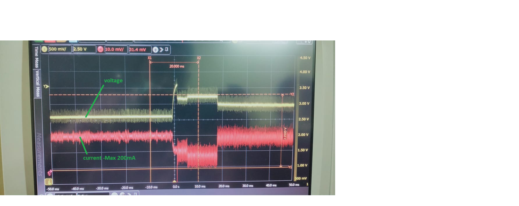
Hello Jom,
Can you share the layout as well while I'm checking the schematic diagram?
Thank you.
Best regards,
Excel
Hi Jom,
Thanks for sharing the data. I will look at it and provide you feedback on Monday.
Best regards,
Excel
Hi Jom,
I will provide my feedback on Friday because I'm currently tied up with urgent case.
Thank you.
Best regards,
Excel
Hi Excel,
Did you check on this query? we are facing same issue in customer board, the situation is very critical. Could you please update this?
Regards
Jom
Hello Jom,
Apology for the late reply.
I compared the PCB layouts of the EVM and the customer boards, and the main difference only was the GND trace between the connection of the output capacitor. See the figure below for details.
I still need to discuss internally if other items might cause a high voltage spike during the decrease in load current.
Keep you posted for any update.
Customer board:
EVM layout:
Best regards,
Excel
Hello Jom,
Apology for the delay response.
The output voltage is set at 3.3V. Is it correct that input voltage (Vin) is also 3.3V (based on the schematic)? And to better understand the issue, please request below items to customer because it looks like the device operates in 100% duty cycle.
1. Same waveform as below but include the VIN and SW pin waveforms. Measure the switching frequency of the SW pin as well.
2. P/N of L28
Best regards,
Excel
Hello Jom,
Just a soft reminder.
Please ask customer to provide a waveform which includes VIN, SW, VOUT and IOUT.
Best regards,
Excel
Hi Excel,
FYI
The issue is solved when we replaced it with a new regulator TPS54218RTER.
Is there any chance of failure with input voltage spike or compensation circuit design ?.
Regards
Jom
Hello Jom,
It looks like the device is already damaged, and the input voltage (VIN) likely went above the absolute max rating of the device. You can suggest to the customer to send the failed part for FA.
By the way, if there is an issue with the compensation circuit replacing it with a new sample will not resolve the issue.
Best regards,
Excel