This thread has been locked.

If you have a related question, please click the "Ask a related question" button in the top right corner. The newly created question will be automatically linked to this question.

TPS73125-EP: Inrush current of TPS73125DBVT

Part Number: TPS73125-EP
The 2.5V output of the TPS73125 is input to the boost DCDC converter of another device and boosted to 3.3V.
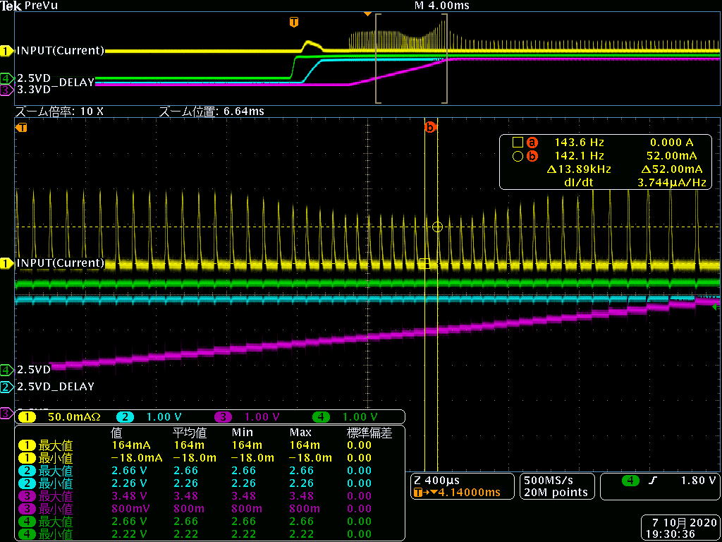
* In the attached waveform, yellow: 2.5V (LDO output) current, green: 2.5V (LDO output), red: 3.3V (boost converter output)

So, let me ask you a question about the Change in VOUT (%) and Iout (mA) graphs in the datasheet.
I have only up to 150mA, but what is the Change in VOUT (%) when Iout is 170mA?
As shown in the yellow waveform, I am concerned about whether the 2.5V of the LDO output will drop due to the inrush current flowing about 170mA.

  • Hello,

    If the 170 mA trips the current limit protection, then the output voltage will droop as the current limit protection takes over, until the 170 mA load is removed.  Due to the fact that these are fast pulses, I think this is less likely as the current limit circuit has a limited bandwidth and probably cannot react quickly enough to the pulses you see in the scope shot.

    What you are more interested in is probably a load transients of 0 - 170 mA and back.  This is a function of your output capacitance and effective Power Distribution Network (PDN) impedance.  You want a very low PDN impedance to eliminate the voltage droop before the feedback loop can react, so plenty of ceramic capacitors in parallel will help.  Polymers are the next best thing, then dry tantalum capacitors for bulk capacitance.  Once the feedback loop kicks in then the output will be delivered additional current from the LDO which will charge the output capacitors back to the regulation voltage.  See figure 22 in the datasheet for load transient test data very close to your pulses.

    Every LDO in the world, whether it is made by TI or someone else, will have a droop on the output during a large load transient because they all have a finite internal bandwidth to react to changes on the load.  The goal is to minimize the droop by adding enough output capacitance and lowering the PDN impedance to absorb the load transient event.

    Thanks,

    - Stephen