This thread has been locked.

If you have a related question, please click the "Ask a related question" button in the top right corner. The newly created question will be automatically linked to this question.

Current sensing amplifier for short circuit current detection

Other Parts Discussed in Thread: INA281, INA293, INA290, INA149, OPA192, OPA377, OPA325

Hi

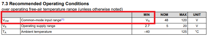
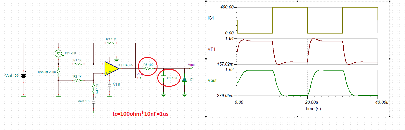
I am working on the Battery Application ( 0 to 100VDC) and measuring the charge / discharge 100A current with shunt method. Now I want to introduce the short circuit detection and protection of power switches. The permissible short circuit current is ~400A for few micro seconds. Please suggest how to detect this current  <10uS.

Thanks

Sandeep

  • Hello Sandeep,

    Thanks for considering to use Texas Instruments.  As you are wanting to detect a short circuit, I expect you will be using a high-side configuration for your current monitor.  Consequently the device needs to survive 100V, which dramatically reduces the options in our portfolio.  Fortunately, we have two devices that can cover that upper bound as well as the lower bound of 0V.  These are the INA281 and INA293 (also comes in automotive Q1 option). Both of these have a slew rate of 2.5V/µs, therefore I think either should be able ramp their output up sufficiently fast to trip a quick comparator or some other cutoff circuitry within 10µs.  

  • Hello Sandeep,

    I saw a message that you need further assistance on this matter.  Can you please help me understand what else you need help with?  I support current monitors and I am not aware of a TI design that fits your situation.  However, if you need a suggestion for either a mosfet to cutoff the current and gate driver to turn off the control FET, I can forward this request to representative of one of those product lines who may be able to better support you on the other stages of your cutoff control circuit.

  • Hi Patrick

    Thanks for the information.

    Please check INA290 current sense amplifier and as per datasheet it has common mode voltage range up to 120V.  Can you please confirm the same.

    Sandeep

  • Hello Sandeep,

    I specifically did not mention that device because of the lower common mode bound you mentioned in your original post (0V).  The lower linear operating range with respect to common mode starts at the supply voltage, which can be as low as 2.7V if your supply is that low.

  • Hi Patrick

    Ok understood. Please suggest with external OPAMPS how this functionality can be achieved.

    Thanks

    Sandeep

  • Hi Sandeep,

    If sensing a high side shunt resistor, most often a discrete op-amp will be in a form of a diff amp.  The small voltage developed across the shunt is rarely enough to push the device into a slew condition, and therefore most often the small signal rise/fall time should be considered.  A back of the envelope calculation is 

    fc = GBW / Gcl,   tR =~ 0.35 / fc

    therefore required GBW =~0.35 * Gcl / tR

    So for instance, if the diff amp noise gain is 100 and you desire a rise time of 3.5us, you'd need a 10MHz GBW op-amp.  So to be more helpful we need to know more details about the circuit such as the shunt resistance, desired output voltage, voltage supply available to power the op-amp, and confirmation that this is high side monitoring.  

    Thanks,

    Scott

  • Sandeep,

    To follow on Scott's explanation, we need to know the details of the application like supply voltages, shunt resistance, whether the application requires high or low side current measurement, etc.

    For example, if it is a high-side measurement with 10mohm resistor using +/-15V supplies, you could directly use INA149 with input common-mode voltage of +/-275V - see below.

    For the same condition but with shunt resistor of 100uohm, you may use OPA192 (10MHz as Scott explained) in gain of 100 - see below.

    Instead of INA149, you could also make your own difference amp using (GBW>10MHz) op amp and four precision resistors.

    All in all, if you need further assistance, we need to have more details of the application as discussed above.

    Sandeep INA149.TSC

  • Hi Marek and Scott

    Thanks for the details.

    I have enclosed the high level details of the design requirements and also placed a schematic to achieve this. But I need to reduce the components count and improve the measurement accuracyCurrent_Sense.docx so design is not finalized yet. But there is another limitation of cost as well, don't want any expensive design also.

    Please suggest and do let me know for any other details.

    Thanks

    Sandeep

  • Sandeep,

    So it looks like you operate on 5V supply and it is a low-side measurement with Vref of 1.5V.

    The precision low-cost option would be to use OPA325 or OPA377 but your circuit is too slow because of 1k||100nF induced long time constant, tc, of 100us - see below.

    In order to allow Vout to settle within few us, you must lower R5 and C1 by 10x resulting in tc of 1us - see below.

  • Hi Marek

    Thanks for the results. Please share the simulation file with me to simulate some more cases.

    Thanks

    Sandeep

  • Sandeep,

    Attached please find OPA325 battery application simulation file you requested.

    Sandeep OPA325.TSC

  • Hi Marek

    Thanks for sharing the information.

    Sandeep