This thread has been locked.

If you have a related question, please click the "Ask a related question" button in the top right corner. The newly created question will be automatically linked to this question.

UCC28951-Q1: Cycle by Cycle Current limiting behave

Part Number: UCC28951-Q1
Other Parts Discussed in Thread: PMP

Hello experts, I have a few issues in my mind about current limiting function of UCC28951-Q1

Our device, which we designed as 30V 35A (max), behaves strangely when its overloaded.
For example
- 35A flows nicely when we connect 0.85R load bank to 30V.
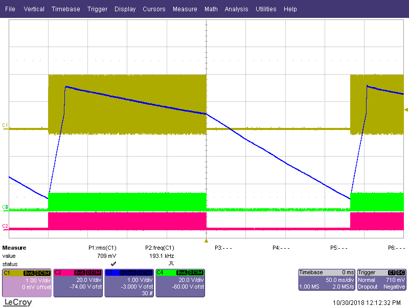
- When we load 0.75R to 30V, the voltage drops directly to 0V, and it acts as if it gets close to 30V again and drops back to 0V, repeating this process constantly It does the same thing when we connect 0.60R load bank to the output , Is this behavior expected or what is the solution?
- When we load 0.75R to 30V, shouldn't it steadily reduce the output voltage to 28.5V to limit the current? same thing when I connect a 0.60R load, shouldn't it reduce the output voltage stably to 25V?

Where exactly do you think the problem is? I would be very happy if you could help me.

Thanks in advance,

Mikail Ünal

  • Hello Mikail

    I think the PSU is operating in Hiccup mode. This is the normal, expected response to a current overload and is described in the data sheet. The easiest way to confirm this is to probe the SS/EN pin during the overload. You should see it behave like this. Yel:CS Grn: OUTD Red: OUTB  Blu: SS/EN.

    Hiccup protection reduces the average dissipation in the PSU and this is why it is the default behaviour for this controller. It's possible to force a Latching OFF or Continuous operation in Current limit if you wish to - let me know and I can supply the details

    Regards

    Colin

  • Hi Expert Colin thank you for you response , sorry but what do you mean with "force a Latching OFF or Continuous operation in Current limit"

    if its possible It is much better to run at the limit we have set, we expect it to decrease the voltage linearly when it is loaded more. thats actually what we want.

    Best Regards 

    Mikail 


  • Hello Mikail

    There are three options for the behaviour of the UCC28951-Q1 in current limit

    1/ Hiccup operation: The unit runs for a while then shuts down for a while then restarts. This cycle repeats until the over load condition is removed.

    2/ Latching shut-down: The controller stops running. There is not automatic restarts like in Hiccup mode. Restart requires either - pulling the SS/EN pin to ground and releasing it or turning the VDD power off and on again.

    3/ Continuous operation in current limit: The controller continues to operate but the output voltage falls due to the current limit - this is the option you want.

    Brief details of how to implement continuous operation are given in the Data Sheet.

    In practice, to give continuous operation in current limit you should place a 180k resistor from SS/EN to GND and a 12k resistor from SS/EN to VREF. The effect is to prevent the internal current sink IDS from pulling the SS/EN pin below the hiccup threshold at 3.6V - The SS/EN pin should be at a nominal 4.35V - or at least somewhere between the two red lines below.

    NOTE: The current sensing transformer is on the primary side so we are actually limiting the INPUT current rather than the output current. The output current limit point will vary if the input voltage varies - going up as Vin goes up and down as Vin goes down. This shouldn't be a problem where the input voltage range is narrow. If you need a true output current limit then you need to sense the output current - see PMP 8740 for an example of how this should be done.

    Regards

    Colin

  • Hello expert Colin, this looks so good!

    I overlooked this feature, it was very nice that you reminded it.


    But can we operate this configuration in "CC/CV mode" also in "paralel operation" if a put a resistor as you said.

    Best Regards

    Mikail

  • Hi Mikail

    The basic CC/CV mode configuration is described in the attached document. This is the method used in the PMP 8740 reference design.

    /cfs-file/__key/communityserver-discussions-components-files/196/8117.CI_5F00_CV.docx

    This gives you a constant output current - useful for battery charger applications in particular - which can be very precise indeed.

    If you want to parallel two power stages and have them share the current then you can do it by configuring two UCC28951-Q1 controllers in a Master/Slave arrangement - Both devices are configured to operate in Peak Current Mode control. The COMP output from the Master is common to both the Master and Slave so that they are both operating off the same current demand signal. If the Master implements a CC/CV characteristic as described above then so will the Slave. Synchronising the two controllers is not absolutely necessary but it is very highly recommended.

    I need to think a bit about the OCP behaviour in the Master/Slave system and I'll update this post shortly - possibly this afternoon.

    Regards

    Colin

  • Thank you for the detailed explanation expert.

    Have a good day.

    Best Regards

  • Hello Mikail

    The  Current Error amplifier should control the output current by controlling the input signal to the PWM comparator (COMP) so that there is never any danger of a current overload of the power stage. The Cycle-by-Cycle comparator on the controller will limit the INPUT current - where the current transformer is situated - so it will provide protection against transformer saturation or a condition where the input voltage has dropped so low that the input current needed to maintain the output is excessive. If the CbC comparator on one of the controllers - the Slave for example - starts to operate to limit the input current (and hence the output current) then the other controller will try to make up the balance and its CbC comparator will also start to operate.

    The overall effect will be that the output power will reduce as the current into the load reduces.

    In view of the fact that the system has both CC and CV error amplifiers you should not enter this condition where the CbC comparators are operating but if it were to happen it would be a 'safe' condition for the power stages.

    Regards

    Colin