This thread has been locked.

If you have a related question, please click the "Ask a related question" button in the top right corner. The newly created question will be automatically linked to this question.

LMZM23601: Vout=Vin

Part Number: LMZM23601

I have been very unlucky trying to get LMZM23601V5 to work on a modular power supply for a datalogger.

The best I could get so far were two units with Vout=Vin. One was reflowed in a controlled temperature oven and the other was soldered by hand with hot air. The only components on the PCB are the LMZM23601V5 and the input (10uF) and output (22uF) capacitors.

Vin is 12.35V. Vout is 12.34V.

There are no shorts to ground that I can find. Current is 0.0A.

Switching frequency at SW is around 15kHz on one unit and 18kHz on the other.

Vin and Vout are stable and both LMZM23601 are cool to the touch.

Adding a 1k load on the output does not change Vout.

Pad11 is connected to ground and has enough copper for heatsinking.

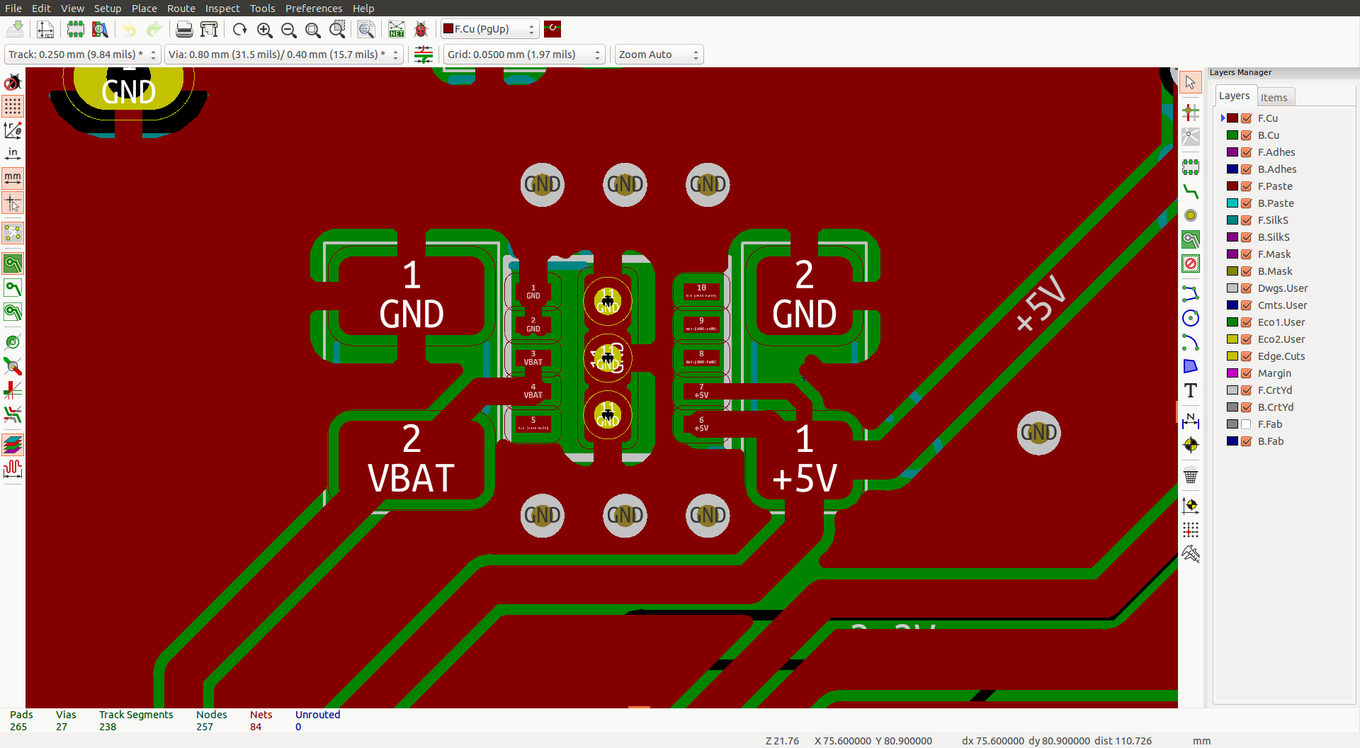
PCB layout. PG is not connected.

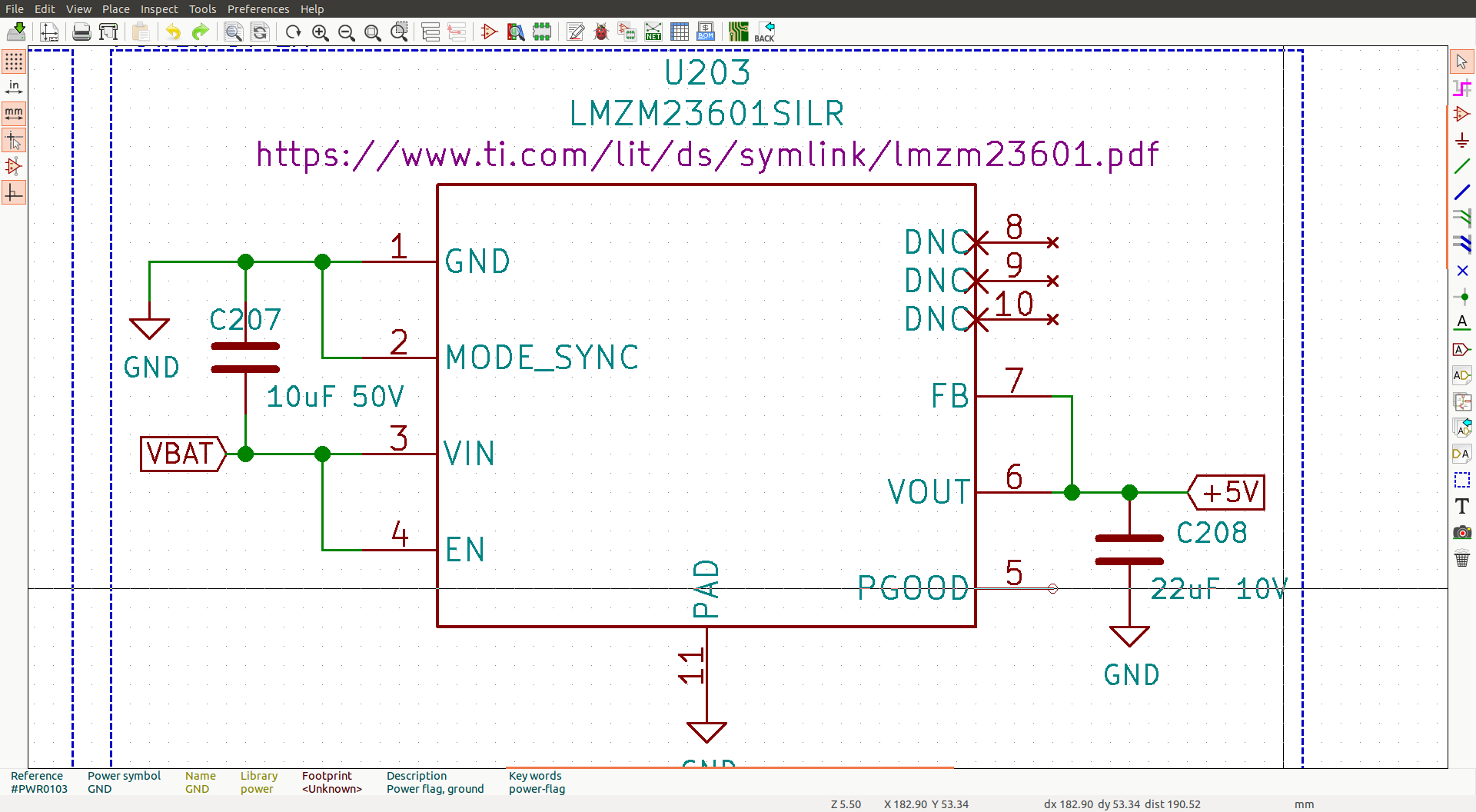
Relevant part of the schematic

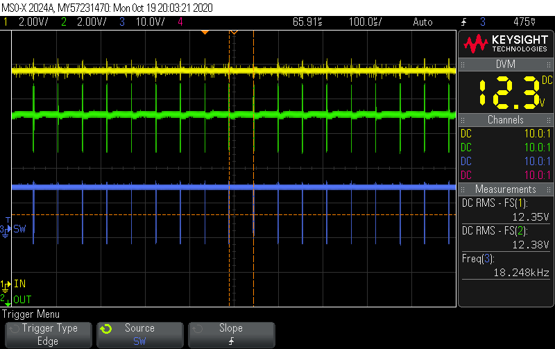
Yellow=Vin / Green=Vout / Blue=SW frequency

What am I doing wrong here?

  • Hello

    I don't see anything obvious that you are doing wrong.  It almost looks like the FB pin is not connected to the VOUT.

    You could try to check continuity between FB and VOUT, even though your PCB snapshot shows a connection.

    Also, be sure that the FB pin is soldered correctly.

    I will consult with our module group to see if there is anything else to look for.

    Thanks

  • With the module in place, I can't really check the continuity between FB and Vout as the pads aren't accessible under the LMZM. I've tested the continuity on blank PCBs and the pads are connected.

    Meanwhile, I reflowed a new module on a new PCB and got the same result. I also removed one of the previous modules and resoldered it - same result. These are the only components on the PCB.

    Right now, I have three LMZ23601 modules with Vout=Vin. They were hand soldered, reflowed and twice reflowed, respectively. Two boards were ultrasonically cleaned and the third still has no-clean flux on it.

    Should I suspect a bad batch?

  • Hello

    I will talk with our module engineers and decide how to proceed.

    I will get back to you before the end of this week.

    Thanks

  • Hello

    Can you tell us what your soldering temperature profile is ??

    What is the maximum soldering temperature ?

    Thanks

  • The maximum soldering temperature is 232º.

    Preheat to 125º for 180s

    Soak at 175º for 120s

    Ramp up to 232º in 140s

    Dwell at 232º for 40s

    Cool down at less than 3º/s

  • Hello

    Thank you.

    I will talk with the module team and get back to you as soon as possible.

    Thanks

  • Hello

    I have some comments and questions from our module and package team:


    1. Where is the device failing initially (e.g. production testing, reliability testing, or field)


    2. Is this a new application or is this application running in volume and since when?


    3. Can you please provide a copy/photo of the TI label of the reel where the devices came from.


    4. This module is rated MSL3-260°C. The peak temp of 232°C seems to be a little low. It is hard to comment on the reflow by description without a plot.


    5. Below are some key parameters of a recommended reflow profile:


    Pre-heat/soaking 150°-200°C     60-120 sec

    Reflow time >217°C             60-150 sec

    Ramp up                       <3C/sec

    Cool down                     <-6C/sec

    Peak temp                     240°-245°C

    Duration within 5°C to peak    less than 30 sec


    6. Please return your failed boards, according to the below procedure.


    For the customer return process please do NOT remove the units from the board as we would like to preserve the failure and not impact and change the failure mode by the desoldering  and handling. However,  at TI we have to destroy the board in order to access the device, pls confirm that you are ok with this process.

    For products purchased directly from TI or the TI store please follow this return request procedure:

      1. Request analysis of suspected nonconforming product using the return request submission form.  Be sure to include picture of the top of the unit (with TI symbol) in the submission form attachment
      2. Upon TI acceptance of the request, return instructions will be provided. Please do not ship products until instructed with a CPR\QEM number.
      3. Follow TI's guidelines for handling customer returns.

    For products not purchased directly from TI or for additional information regarding TI customer return policy, please see  http://www.ti.com/support-quality/resources/customer-returns.html

    Thanks

  • Hi,

    The device is failing at production testing for a new application.

    We are redesigning the power supply module of our application to improve efficiency. The LMZM module is replacing an LDO.

    These failed units all came from samples requested through TI (sales order T00927166) - unfortunately I no longer have the antistatic bag with the reel information.

    The reflow profile I'm using, apart from the peak temperature, seems to agree with the suggested reflow profile. Ramp up is <1ºC/sec, and time >217ºC is > 60s.

    I'm OK with sending a board for inspection. 

  • Hello

    Thank you.

    Please use the above instructions to send the failed boards to TI.

    Thanks

  • Hi,

     I already submitted my return request. I'm waiting for an answer.

    Thank you for the help.

  • Thank you Afonso for the update.

    Regards, 

    Denislav

  • Hello

    I will close this post.

    The issue is being worked on offline.

    Thanks

  • Hi,

    With a module from a different batch it worked as expected. I hope to hear from the lab results.

    Thank you for the help.