This thread has been locked.

If you have a related question, please click the "Ask a related question" button in the top right corner. The newly created question will be automatically linked to this question.

BQ77915: Short circuit protection feature is not working

Part Number: BQ77915

Hi,

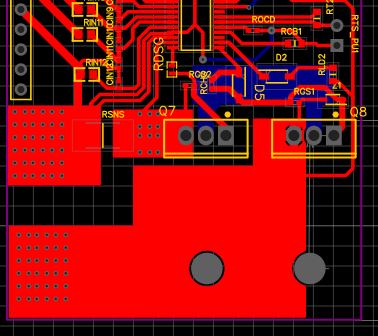
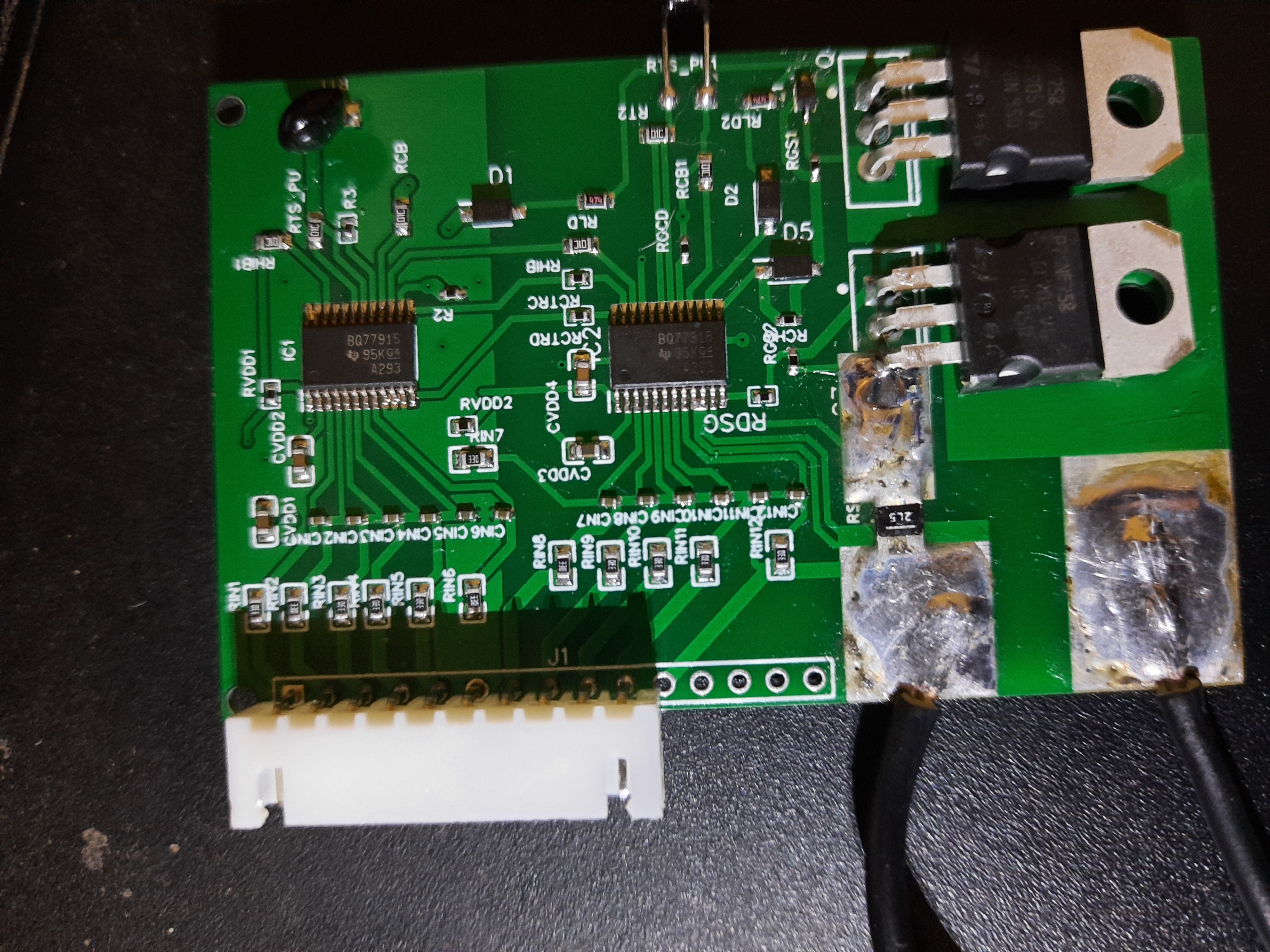
I am using bq7791500PWR device, I used 487K resistor to set OCD delay. Everything in the circuit works well except short circuit protection. When I first tested a prototype everything worked well, Later I made PCB compact from then I have tested multiple boards, I couldnt find the error, Please help and what components should I cross check?, does the placement of Rld resistors make difference?

  • Hi,

    The placement of the Rld resistors is important, as it affects the load removal/detection feature of the device which is needed to recover from certain faults. For correct placement, please follow our schematics in the datasheet as well as the EVM user guide. 

  • Hi..

    Shawn.. I have gone through data sheet and EVM guide already... there is no proper guidance for rld resistor placement.. could you please suggest the placement of Rld resistors or else point out some references.. my 4 boards literally burned like anything.. I am trying hard to figure out the problem

  • Hi,

    The best reference we have is the EVM.

    It is possible that the problem may be due to another reason. Could you describe the problem in more detail?

  • Hi,

    1. When Pack + and Pack - are shorted device should automatically trip and turn off the FETs, right? , This is not happening.

    To set OCDP delay, i used a 487K as recommended in the datasheet, LD pin is connected to Pack- with 470K. All other features of device are working well, except Short-circuit protection

    2. I have gone through EVM user guide again as you recommended, My schematic matched with it. What could be the potential error that I should check for?

    3. Should I place Rld resistor close to Pack- or device?

    4. I found that Diode D5 across RCHG is connected reverse, But i don't think, this is the one that created issue? Is it?

    5. Another issue is, when i measure resistance between Pack- and LD pin resistance is 1.212Mohm, Is this the problem? 

    6. I understand that once short circuit is detected and, If Load detection doesn't work, It will again turn on the FETs. Am i right? 

    Please find the image of damaged PCB and all values of components, Kindly help

  • Hi Shawn can you please reply to my previous post? , Should I change RLD2 resistor value and delete the bottom diode?

  • Hi,

    Shorting the PACK- and PACK+ pins is not the correct way to check for a short circuit event. The device will detect a short circuit event if (VSRP – VSRN) < VSCD for tSCD_DELAY. 

    I would recommend placing the Rld next to the PACK- rather than the device, but I am unsure if that will make a difference. 

    I would also recommend making sure that your diode is connected properly. 

    The resistance between the PACK- pin and the LD pin should be around 450kOhm, not 1.2M Ohm. That problem should be addressed. 

    SCD fault requires load removal to recover, so the functionality of the LD pin is critical.