This thread has been locked.

If you have a related question, please click the "Ask a related question" button in the top right corner. The newly created question will be automatically linked to this question.

BQ29700EVM-610: Using the BQ297XX for Series and parallel circuits

Part Number: BQ29700EVM-610
Other Parts Discussed in Thread: BQ2970

Related Question: https://e2e.ti.com/support/power-management/f/196/t/760610

Hi I want to use the BQ297XX IC to make a Per-cell protection IC circuit for N parallel and N series packs or N Series and Parallel packs

(NSNP or NPNS)


Here is an example system level topology

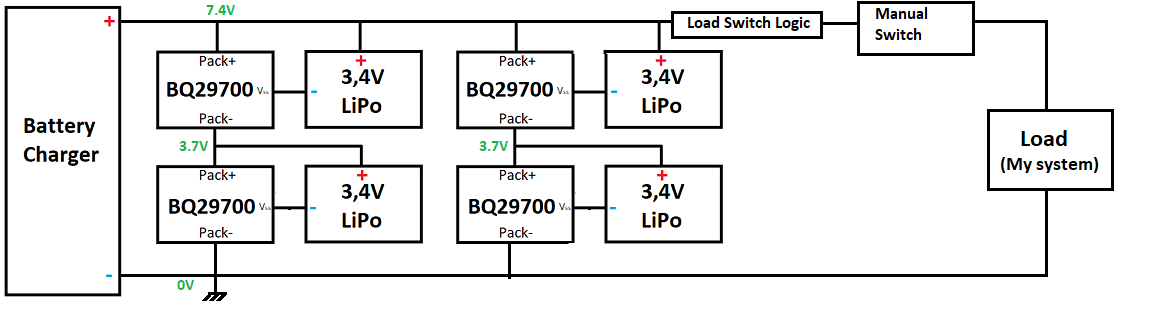
In the related  question it was explained that a problem could occur in a series connection due to an UVP problem causing -3V across the V- and BAT pins. That is V- was more positive than the BAT pin.

Of course putting more cell+ BQ297XX IC 's  in parallel would prevent this from happening because the Load would still be powered but the issue can still occur resulting in part failure.

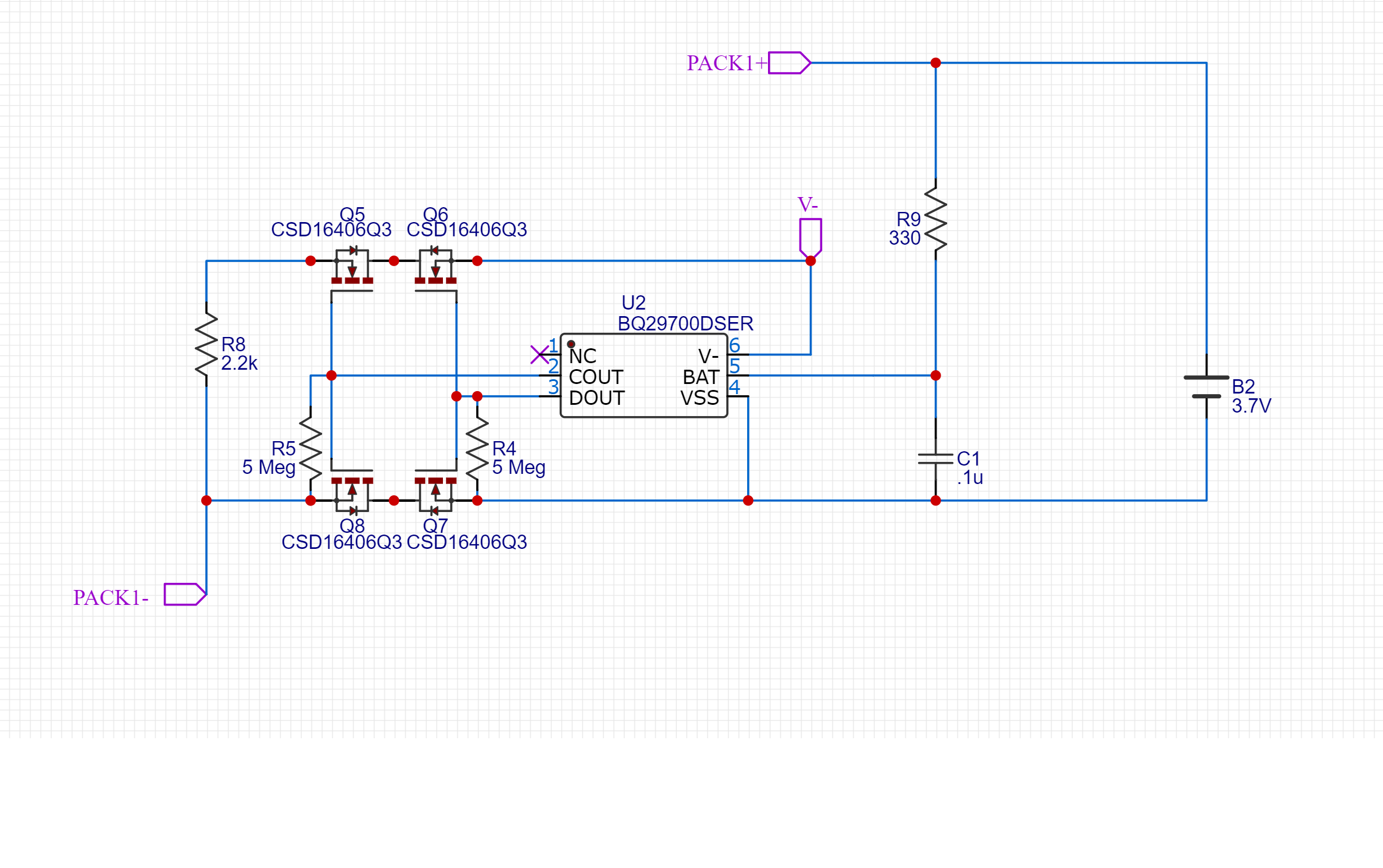
I am wondering if the addition of Q5 and Q6 below could prevent an UVP condition from causing problems and if there are any other foreseeable problems, and if allowing this IC circuit to be used per cell in the above NS + NP circuit  would work.

Thank you

  • Hi,

    I would recommend using a single protector chip that can handle the number of cells in series that you are trying to support, rather than using several BQ2970 ICs. This will save board space and simplify the design. The BQ2970 should only be used in battery packs with a single cell in series. 

  • Hi Shawn,

    Thanks for your response but I don't care much about board space but more if the protection IC will be able to support per cell protection.

    This would allow scalable inclusion of any number of Series and Parallel connections and more protection in general

    Is there any reason why the design will not work with the addition of Q5 and Q6?

  • Hi,

    It is possible that this solution could prevent issues, but I believe that the best solution would be to choose a battery protector better equipped to handle the appropriate amount of cells in series. 

  • Would a diode work instead of Q5 and Q6? V- to the 2.2k resistor?

    It seems that the transistors use the V- pin to sense certain conditions to trigger COUT and DOUT so the transistor method wouldn't work.

  • Hi,

    It will be difficult to speculate since we have not done any testing on this configuration. The V- pin is the voltage sense pin, so it is very important to the functionality of the device. If this pin is not configured as described in the datasheet, the device could enter fault mode unexpectedly.