This thread has been locked.

If you have a related question, please click the "Ask a related question" button in the top right corner. The newly created question will be automatically linked to this question.

BQ29700EVM-610: Doubts about series connection, reverse voltage protection and protection circuit levels

Part Number: BQ29700EVM-610
Other Parts Discussed in Thread: BQ29200

I now that this integrated circuit is a first level battery protection device and usually it is embedded in the battery protection circuit, but can I use it as a second level protection circuit?
I mean, in my circuit design I want to provide the possibility to use (removable) batteries without built-in protection circuit, so I thought to utilize the BQ29700 in my PCB. Can I do it?

For the batteries that already have a built-in protection circuit, I think it could be seen as a redundancy circuit.

If it is possible, do I have to implement reverse voltage protection diodes?

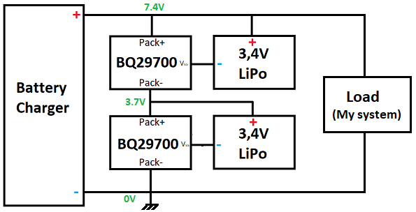
Another doubt is that for my project I need 2 series cell battery pack (7,4V LiPo), but the BQ29700 IC is suitable only for single cell batteries, so, can I stuck two BQ29700 in series and each protection IC is in parallel with its battery? I attach the block diagram of what I have in mind:

Any suggestion?

Thank you for your attention.

  • your question has been assigned to an AE, it will be answered today.
  • Hi Mariglen,
    When looking at a part for primary or secondary it is often a choice of where the thresholds are selected. Whether primary and secondary or just redundant, another consideration is to be sure each protection mechanism can recover (if appropriate) if both are tripped.
    You would need to determine appropriate behavior for your system design. Our selection of 2S protectors is very limited, the bq29200 is a 2S overvoltage protector but has only 2 threshold values which may not be appropriate for a 3.4V cell.
    In the circuit diagram shown, if one of the BQ29700 devices protected with a load instead of a charger, the voltage would reverse on the protected "pack". V- is not allowed to go to 3.4V above BAT. You will likely need to combine the COUT and DOUT from both devices with some logic to control a common set of protection FETs. It may take some circuitry, we do not have a reference design using 2 devices together.
  • Hi WM5295,

    Thank you for the reply.

    Sorry but I forgot to indicate the load in my block diagram:

    Obviously when the battery is charging, it is disconnected from the system and the system is powered by a 12V stabilized power supply.

    what do you mean with "protected with a load instead of a charger"?

    I'm attaching the datasheet of the battery that I'm going to use, in which you can see that it has a built-in protection circuit similar to the one shown in the BQ29700 datasheet.

    GMB503465 1300mAh Li-ion Polymer Battery.pdf

    I think that putting 2 of these batteries in series is like forming my block diagram, or am I wrong?

    Morover, the BQ29700 has lower threshold values than the built-in protection circuit, so I think that it will trigger befor the built in protection (safer).

    I had already noticed the BQ29200, and yes, it's not so appropriate for my case.

    Regarding V-, each V- is related to its Vbat so I think that V- never exceeds Vbat+0.3V: for the bottom section I have V- = 0V and Vbat = 3.7V, and for the upper section I have V- = 3.7V and Vbat = 7.4V...it seems ok.

    Where am I doing wrong?

  • Hi Mariglen,

    When in the system without the charger, if the top cell were to go to UV for example and protect, the load would pull the voltage across the pair of cells to 0V.  Since the lower cell is still powered (3V in this example), and the sum of voltages around a loop must be 0, the upper cell would have -3V applied.  

    In the BQ29700 circuit this would drive the V- pin greater than BAT.  Looking at your battery specification the PCM section seems to describe a circuit like the bq29700.  Section 8 includes "Do not reverse the positive (+) and negative (-) terminals."  If the PCM protector of the upper battery opened first the result would be similar, the bq29700 would loose power opening the FETs.  Since the FETs associated with the bq29700 circuit are open it is not clear if the cell would see negative voltage or not.

    Be sure to think of these type considerations when stacking protectors or protected cells.

  • Thanks a lot. This was very clear and exhaustive. I will think of a solution to this problem.