art Number: TPS56121
Hi team,
Could you help me to find an appropriate value for inductor and loop compensation RC?
I'm trying to design TPS56121 in the operating condition of 10.8Vin, 5.5Vout, 2.8Aout. The load is quite low but customer wants to design with this device as it's a registered device. So I want to find a way to design the required power rail with this device rather than recommending another device to customer.
1. As the low load current requires too large inductance, I want to set fsw 1MHz. But Webench sim runs with 500kHz fsw but doesn't run with 1MHz fsw. Is this a Webench error or is this device not supporting 1MHz in this operating condition? Plus, if fsw is 1MHz, 3.3uH is okay to satisfy 30% of Iout. But customer wanted to have fsw 500kHz at the beginning. Then the L should be doubled, right?
![]()
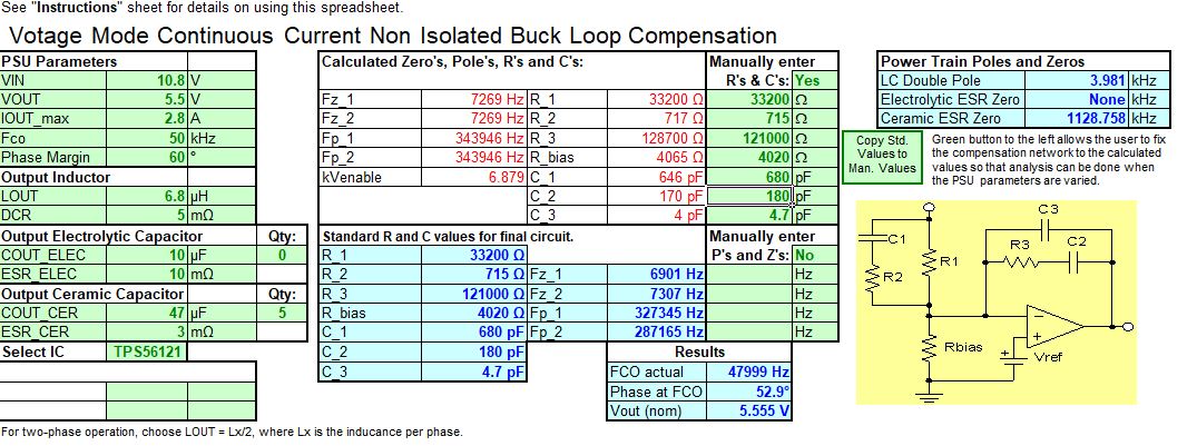
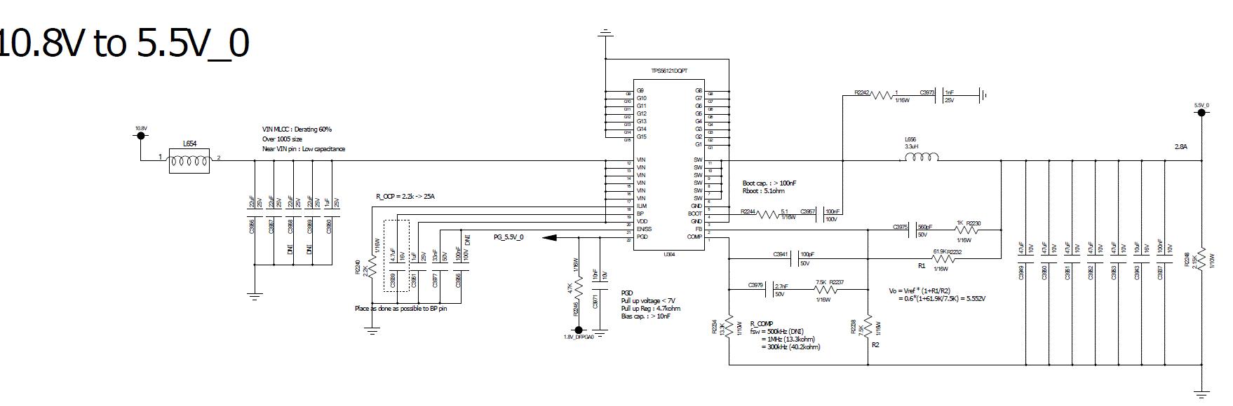
2. In regard to the loop compensation components, please refer to the attachment. They are using 3.3.uH inductor and 47uF*5+10uF*1+100nF*1 output capacitors.
- Current design values_TPS56121 Cal.xls : current customer design. It's not stable.
- Schematic Review_TPS56121 Cal.xls : As R_1 is recommended to be 10k to 50kOhm in datasheet, I changed values of R and C. But I'm not sure I tuned L, fsw, and loop RC values correctly. Would you check it and recommend any value? Otherwise, you can let me know the way how to choose these values correctly other than this excel sheet.
 Current design values_TPS56121 Cal.xls
3644.Schematic Review_TPS56121 Cal.xls
Thank you for your prompt response! Customer is waiting for any feedback..