This thread has been locked.

If you have a related question, please click the "Ask a related question" button in the top right corner. The newly created question will be automatically linked to this question.

TPS737: How to deal with EN pin?

Part Number: TPS737
Other Parts Discussed in Thread: TPS7A45

1. When the EN pin is not used for switch control, there are two ways to connect the EN pin,One is directly connected to VCC, the other is connected to EN after two 10k resistors are divided;

    Under the normal working condition of chip reverse current protection, which connection method is more reasonable?

2. Does TPS73733 have a minimum load requirement?

  • Hi Rengui,

    Using a voltage divider would be better for reverse current conditions on the enable pin.  This is because the voltage will be divided down, giving a better probability that the EN pin voltage will be lower than 0.5V which is preferred during reverse current operation (see section 7.3.4 in the datasheet).

    There is no minimum load requirement.

    Thanks,

    - Stephen

  • Hi Stephen,

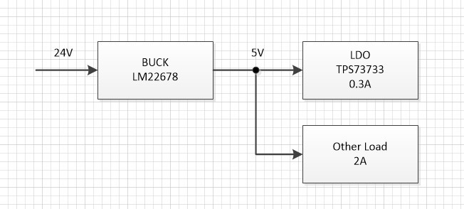
    1. What is the maximum capacitive load of TPS73733? The 5V power supply in the picture has two loads, one is 0.3A and the other is 2A. The output capacitance of TPS73733 is relatively large. When the voltage of EN pin is greater than 0.5V when power is off, the capacitance may be discharged through TPS73733, which will cause the chip to fail?

    2. Do input and output need 100nF decoupling capacitors?

    3. What is the recommended input-output differential pressure? Chapter 6.5 is 130mV ~ 500mv, but figure 2 in Chapter 6.5 recommends 1V。

    4. What is the input current of TPS73733 when the output is short-circuited?

    Thanks,

    - Rengui

  • Hi Rengui,

    From a stability perspective there is no characterized maximum load capacitance for this device.  If you feel that your maximum load capacitance is very large you can purchase an EVM to conduct a load transient test to assess the stability.  At a minimum I would expect hundreds of microfarads to be fine.  Even though the TPS737 has reverse current protection, if you operate in a mode where reverse current can flow then you will want to limit the amount of current to 5% of the rated max.  That would be 1A * 5% = 50mA.

    100 nF input and output capacitors are helpful when the LDO is not close to the source supply or load.  The main issue is inductance in the PCB or harness, connecting the source to the LDO and / or also connecting the LDO to the load.  In this case the 100 nF improves the power integrity from the source, and also mitigates the reactive impedance on the load.  If your LDO is on a small PCB with the source and load nearby, you likely do not need the 100 nF capacitors.

    The recommended headroom voltage (Vin - Vout) is 1V.  This is a common industry standard value, especially for older designs like the TPS737.  The minimum is what you see in Chapter 6.5. The difference is that the minimum is what is necessary to maintain regulation on the output but it is better to design with more headroom than the minimum required.  As you increase headroom voltage, certain metrics improve like PSRR and noise because the internal circuitry has more operating voltage to work with.  At a certain point increasing the headroom voltage does not give you any further improvements but can cause unnecessary power dissipation and thermal increases across the device.  So while you do not need to operate with more headroom voltage than what is seen in Chapter 6.5 to maintain regulation, it is better to use 1V.

    The short circuit current is typically 450 mA.  This is listed in the EC table and also in figure 10 by the dashed line.

    Thanks,

    - Stephen

  • Hi Stephen,

    1. Do you have a way to limit the reverse current to 50mA? The 5V in the circuit has a large 2A load. When the system is powered off, if the 5V power is consumed faster, the 3.3V load capacitor will discharge the 5V power, and this current is not easy to control.

    If there is no way, are there other LDOs with reverse protection?

    2.Is the average current value or the transient current shown in Figure 10?

    Thanks,

    - Rengui

  • Hi Rengui,

    Question 1:
    The reverse current would be limited by the application circuitry, the LDO would not be limiting the reverse current. You typically need to insert some new component or small circuit to perform this function. A series schottky diode in front of the LDO would be enough to limit the reverse current in all cases.

    If you are using a resistor divider on the EN pin from Vin then you meet the datasheet criteria of driving the EN pin low before removing Vin.  In that case you do not need any additional components as the device will always provide reverse current protection.

    If you want to pursue a different component, the TPS7A45 is an option.

    Question 2:
    Figure 10 shows the current limit of the device.  In modern LDO's the current limit has a feedback loop which takes somewhere around 50 us to kick in once the current limit threshold has been exceeded. 

    Thanks,

    - Stephen