This thread has been locked.

If you have a related question, please click the "Ask a related question" button in the top right corner. The newly created question will be automatically linked to this question.

WEBENCH® Tools/LM5175: I can't start the circuit ... No generation.

Part Number: LM5175
Other Parts Discussed in Thread: LM5176, MSP430FR5972, CSD16321Q5, CSD18563Q5A, LM25122-Q1, LM5122ZA,

Tool/software: WEBENCH® Design Tools

I can't start the circuit ...

No generation.

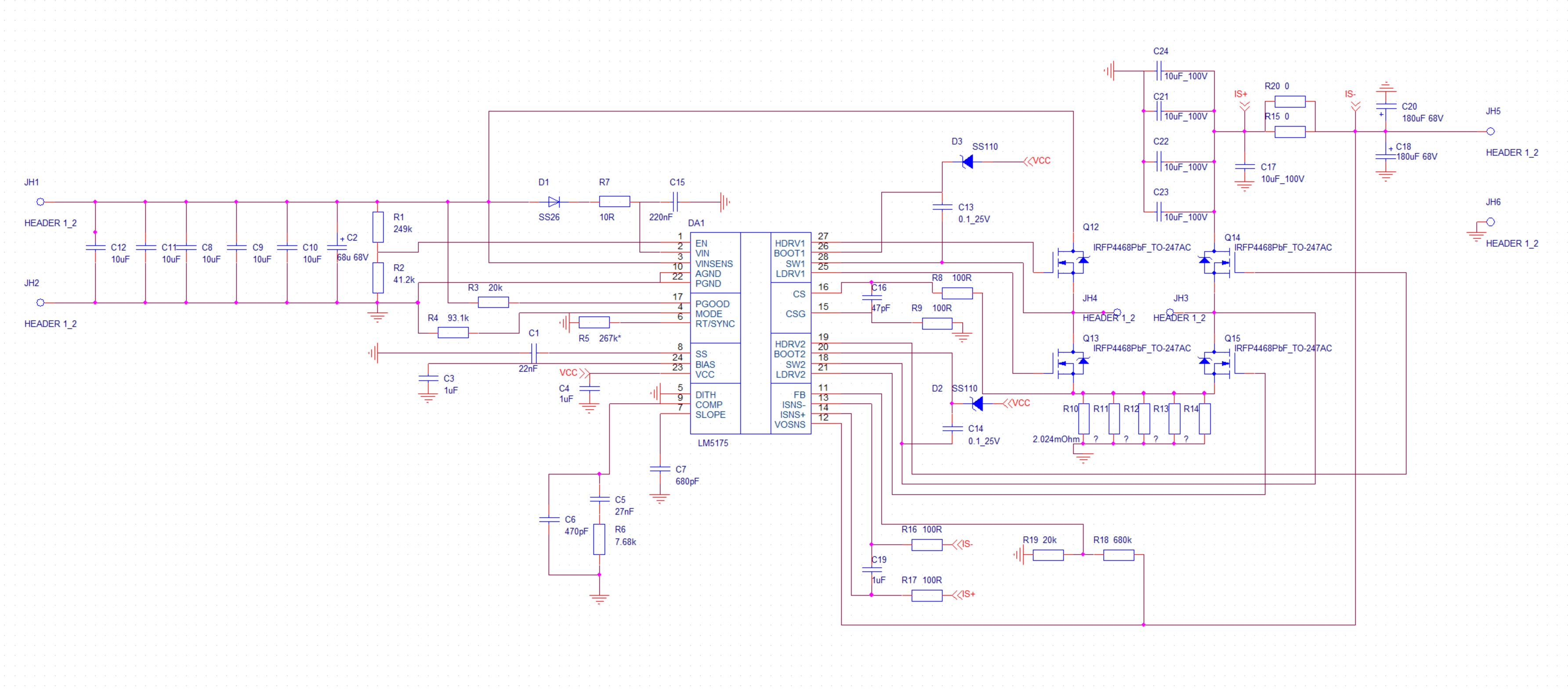
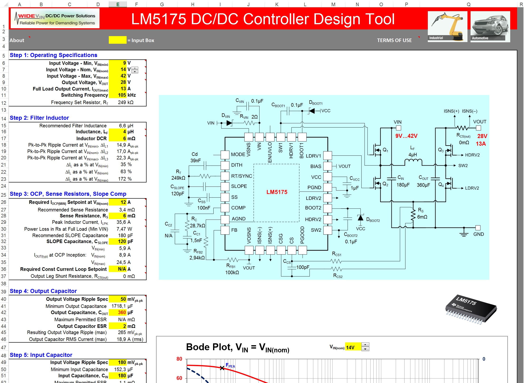
the scheme that Webench squeezed out to me is complete nonsense, does not correspond to the scheme that the "initial installation" of Excel tables from TexasInstruments does.
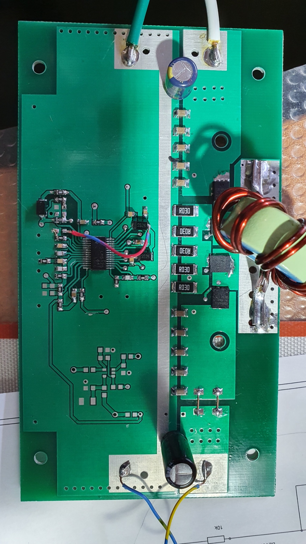
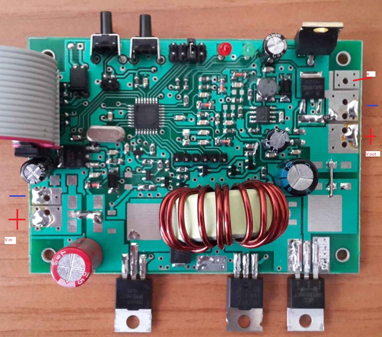
See attachment.

What to do ?

Please, Just don't advise me to use Webbench!

I am interested in the answer from real people who made power supplies on LM5175

What is my mistake?

 LM5175 Buck-Boost Quickstart Tool -- r9.pdf

  • Hi Alexander,

    Thank you for posting.  Our engineer will study this case and get back to you next week.

    Thanks,

    Youhao Xi, Applications Engineering

  • Hello Alexander,

    As you already know that you want to use the LM5175, I recommend taking the result of the Quickstart Tool for your design.

    Normally the Webench result should not be complete nonsense as you mention, so I would be interested which issues you observe. In general there are more than one solutions to the same problem, but it might be possible that there are points in Webench we need to clarify, so more information would be interesting to make the tool better.

  • 1) thanks for your answer.

    2) English is not my "first language", so if you do not understand something, I ask you to clarify what exactly I wrote is not clear. Thanks.

    3) I would apply the word "delirium" to what Webench generated for me. But my circuit also has minor bugs, which I fix. In the attachment - the SVG file of the electrical circuit that Webench made for me for currents of 15Amps = (WBDesign15) And what he did for currents of 6Amps Pay attention to Dboot diodes and D2. Now compare this diagram with what the LM5175 Buck-Boost Quickstart Tool produces. Crazy ...

    4) Why do you need to energize the Pgood leg? After all, this is a transistor that is turned on by the internal logic of the microcircuit. If I do not use this signal, then why put a 10-20kΩ resistor on it and connect it to the + power supply? This makes no sense.

    5) I did not find an answer to the question: can the LM5175 microcircuit operate at frequencies less than 100 kHz from an external signal generator?

    6) I think that my problem is that the LM5175 cannot swing the electrical capacitance of the control electrode of the field-effect transistors that I used. Now I am doing experiments with different components, I will publish the final working circuit here (if I can get the LM5175 to work).

    7) I really like some Texas Instruments products (especially MSP430FR ...), but your descriptions (datasheets) make my brain boil :)

    WBDesign6-15.zip

  • Here is an oscillogram of the real operation Gate of the Q12 transistor (my circuit)

    and the WBDesign Gate transistor M1 - (WBDesign circuit).

  • Hello Alexander,

    2. Same for me, so please tell me as well if something is not clear in my answers.

    3. I will check why there is such a discrepancy between Webench and the Quickstart tool for your design requirements. Are the values you have in the quickstart pdf the ones I shall use or is there possibly a change in your system since you created this? E.g. in the quickstart tool you use 13A, but the Webench designs seem to be for 6A or 15A.

    4. Webench does not know if you want to use PGOOD in your system or not, so it assumes you want to use it and adds a resistor. You do not need to add it if you do not want to use this signal.

    5. No, the minimum recommended frequency set with the external resistor is 100kHz and the synchronization signal shall be higher than the set frequency, see p.16f in the datasheet for this description.

    6. Please use the quickstart tool for checking which components cause which power dissipation. It is for sure not perfectly matching with reality, but at least it is a good starting point, I think.

    7. Let me try to answer the questions you have, but please be specific :-)

    According the scope plot: I expect that you measured the gate signal with reference to GND, but the gate signal of M1 needs to be referenced to SW1.

    For debugging the circuit, please measure SW1 and SW2 at the same time, as the device decides internally on which side it will switch in the next cycle.

  • Thanks for your answer.

    1) My initial idea was to use the LM5175 to create a power supply with an input of 9-30 volts, an output of exactly 28 volts and currents of 15 amperes. This is what I want to get. I started experimenting with "software emulators", and according to their data, it turns out that the schemes are very different.

    2) I have lowered my requirements to 13 amps at 28 volts output. I wanted to understand how the schema changes. I do not need exactly 92% efficiency, I need compactness and power, the ability to work 24 hours a day.

    3) question: can I use several such identical circuits in parallel to obtain, for example, to obtain an increase in current? those. for example, one circuit outputs 13 amperes, and two 2 * 13 = 26 amperes? Is it necessary to decouple one circuit from another with a Schottky diode?

  • Hello Alexander,

    1. 420W might be a bit high for a single 4-switch buck-boost. I think paralleling 2 devices like in point 3 below with 210W each should be possible. The high power might be as well the problem with Webench, but please give me some time to check the details.

    2. I think even with 350W, it might be hard to get the power dissipation out of the converter. With 92% we are speaking about 30W power dissipation.

    3. Please check out this app note for paralleling such a device: 

  • Thanks for your reply.

    question: if I need to get in one circuit, one converter, at the output of 20-30Amps at 28Volts, with an input range of 9-30volts, which of the chips (converter chips) of Texas Instruments is preferable to use? (if not speaking from LM5175).

  • question: what is the difference between LM5175 and LM5176? I read the datasheet and did not understand the difference between them.

  • Hello Alexander,

    LM5176 has frequency dithering feature, but does not have DCM feature.

  • I have now remade the printed circuit board for the use of the recommended transistors, as in the "example for beginners". When the board is ready, I will take measurements and unsubscribe. This will take time ... I can say that the use of other field-effect transistors in the TO-220 package leads to very strong distortion of control pulses. I would ask (recommend) in the descriptions and "manuals" to pay special attention to the fact that LM5175 can only work with field-effect transistors Texas Instruments.

  • Hello Alexander,

    I am sorry that you have issues with the LM5175. The device does work with a lot different types of FETs, not only ones from TI.

    The problem you might have encountered with TO-220 FETs is that the current loops get big when a FET with a big package is used. Another possible issue is the gate charge your FETs might have, high gate charge need high peak currents.

    I am looking forward to see the results you will have with the new layout.

  • Нi Brigitte

    1) You have nothing to apologize for. Texas Instruments is doing a great job of developing new chips and new solutions, microprocessors. I really like some solutions, I am sorry that in my work I cannot use more components from TI, because the USA is very far from us and our local distributors of radio components do not carry most of the items from TI, and what they carry has a 60-120% markup from the TI price.

    2) The "gate charge" of the field-effect transistor really plays a role, as well as the voltage at which the field-effect transistor is controlled. I tested several transistors from the IRF, but their parameters are worse than those of the TI. Therefore, I am upset that the LM5175 is designed to use TI field-effect transistors with unique parameters, but at the same time I understand TI, and I understand that the solution must be balanced: the best parameters are achieved using the best components. And if one company wants to do something well, it has to make the best parameters for all the components from which the device is assembled. Therefore, I continue my research.

    3) In my opinion (and I worked a lot with Atmel, IRF, PIC, STM) TI should write more understandable instructions :) (datasheets). I pretty much broke my brain when I studied how the MSP430FR5972 works, I spent about a month to check in the work what I wanted to achieve from this microcontroller. But when I figured it out, I was able to write a very beautiful program code, and now MCP430FR5972 is used in all my products. I hope it will be the same with LM5175. :) I will figure out "how it works" and solve my problem.

    Thanks for your (TI) help.

  • Hello Alexander,

    Please review the LM5175 EVM and you will observe that it is not using TI MOSFETs: 

    The part can work with a lot different MOSFETs from different manufacturer, but it seems to be difficult to convince you :-)

  • No need to convince me :-)

    I read datasheets.

    LM5175 gives out about 8 volts to control field-effect transistors (this is output 23 VCC what is issued to the drivers), and it is limited in the driver current (2 amperes).

    Most field effect transistors have (require) gate control from 10-12 volts.

    This immediately narrows down the possible options for transistors to "controlled from TTL logic" (up to 5 volts to control field-effect transistors). And if we also take into account the parameter "gate charge value", then the choice of field-effect transistors becomes very small.

    I've tried several different transistor options. Those field-effect transistors with "TTL control" worked best of all, but they have a very high electrical capacitance of the gate, therefore, a large current is required, and we have only 2 Amperes ...

    Therefore, it logically follows that from the whole variety it is possible to use only field-effect transistors of the latest generations of the name TI, they are just suitable in terms of parameters (described above).

    Transistors from IRF in TO-220 are not suitable.

  • Hello !

    Miracles continue ... :(

    1) I completely redesigned the PCB. See the picture.

    I used the recommended field-effect transistors manufactured by Texas Instruments.

    2) Q1 + Q2 according to your scheme are CSD18563Q5A, the second pair is CSD16321Q5

    3) When the circuit is started from a 12volt input battery, a strong whistle is heard from the inductor (inductance), the light bulbs in the load (I used incandescent bulbs as the circuit load) start to light up slowly, the Q1 transistor heats up to a high temperature. The circuit cannot reach an output voltage of 28v ... The oscillogram of the control of the Q1 gate (between pins SW1 and HDRV1) is shown in the picture Q1-Q2. As I understand it, the Q1 transistor heats up because it cannot fully open (3.2 volts on its control instead of 8.5 volts like all other transistors). Why is that ?

    4) when the transistor Q1 burned out and became completely "conductor" (its resistance in the open state became equal to zero ohms). The circuit works great and gives me 28.2 volts out!

    5) what's the problem? I have completely assembled the circuit as recommended by your program. I used the required transistors. Why does Q1 burn out?

    I understand that now my whole circuit works as a step-up, and after the combustion of u1, the circuit will not be able to work as a step-up.

    I need an input voltage operating range of 9 volts - 42 volts.

    What should I do ?

    LM5175 Buck-Boost Quickstart Tool -- r10.pdf

  • Hello Alexander,

    Can you please test your circuit first with a resistive load?

    A light bulb is a horrible load for a converter as it is a short before it turns on.

    Therefore it is necessary to check the converters functionality before loading it such specific.

  • Hi !
    to resistive load, this circuit works exactly the same.
    I used a lamp of 24 volts 15 watts in my tests.
    After the first transistor burned out, the circuit began to work perfectly.
    Before that, the first transistor is always very hot.
    This is not my first year in designing electronic circuits, and it is very unclear to me why the circuit works this way. I made circuits in which a SEPIC converter works using 1 p-type and 1 n-type transistors.
    My circuit worked from 8v to 25 volts (input) and the output was supported at 15 volts and 13 amps.
    Do you have any ideas how to help me?
  • Here is my serial product - a pulse (special algorithms) charger for batteries.

    SEPIC converter for 15 amp output current, input 8-24 volts.

    I have been producing this device in series since 2013, as a control and control generator for Atmega8.

    Now I want to switch to MSP430 and as a converter 9-42 volt input and up to 28 volt output on your lm5175 microcircuit.

  • Hello Alexander,

    Sorry for the delayed response, I was out of the office during Christmas season.

    When you mention that the circuit works perfect as soon as the first transistor burned out, I expect you are speaking about Q12 in your schematic and you are testing with the input voltage being lower than the necessary output voltage.

    In addition, you mention that the behavior is the same when there is resistive load on the output and no light bulb. Can you please check the startup of the circuit when there is no load attached? Does it then start to 28V? Is the transistor then still getting hot?

    With this high current and power, I recommend to replace Q12 with 2 transistors in parallel to split the power dissipation in it.

    You are using 6 mOhm sense resistors in your layout (5 times 30 mOhm) (your schematic shows 2.024 mOhm), with 6 mOhm, the maximum current allowed through the transistors is too low for your maximum output current. This means that the converter is permanently operating in current limit, if you draw 13A. So it cannot achieve 28V.

    In step 3 of the quickstart tool, a IOCP of at least 15A needs to be set for your application, so a sense resistor of maximum 2.8 mOhm is recommended.

    Please review this article for the connection to CS and CSG: 

    Other Parts Discussed in Post: LM5175 In my last blog , I provided tips for optimizing hot loops in a buck-boost converter. I decided to add this tip as a separate topic after finding it in almost all…

    Please reduce the slope capacitor to 120pF maximum for the first tests. Smaller cap there makes the power supply normally more stable when in buck-boost mode.

  • Hi Brigitte!

    Thanks for your reply.

    1) As for the "current sensors and tracks to them": I just can't make 4-6 layers of a printed circuit board, just in order to meet all your conditions :-)

    So a given in 2 layers of a printed circuit board is what I can't change ...

    In my board design, I have a 35 micron copper fill so I can neglect the noise. One must always remember the "current paths" and think graphically (draw) how the "fault currents" will pass through the copper layer. Then everything is OK and there will be no problems. All the taps from the shunts on my board go on the lower (back) side of the board, there is also a "ground" there, but the main short circuit "on earth currents" is the upper part of the board, there is a fill with "ground" to the maximum, currents are closed at the top copper boards (paths of currents).

    On one of the boards, I ran a circuit from the current sensors to the LM5174 terminals with a separate coaxial cable, this did not change anything in its operation :-)

    2) I eliminated the first two transistors (Q12 + Q13), and made a jumper instead of the first, after which my circuit began to work perfectly as a "up" boost converter (9-12v to 28v). I excluded the second transistor (Q13) from the board, because, despite the fact that it should always be "closed" (high resistance), it still receives the "needles" of the opening control from the LM5175. This led to the Q13 warming up to 150C degrees during operation. It is unacceptable.

    3) I think I am done experimenting with LM5175 and I can say this:

    a) LM5175 is not designed for powers above 80-100W, because there are many problems with the PCB layout and the used transistors.

    b) LM5175 is designed to build small-sized low-power (up to 80-100 W) high-efficiency converters.

    c) for my purposes, I need to revise the original terms of reference, applying simpler solutions, and abandon the simultaneous support of step-up and step-down modes.

    For example, switch to two-transistor circuits lm5122za or lm25122-q1, which already have a simple master-slave mechanism to increase power.

    Thanks for your support and links to docs, it was very informative.

  • Hello Alexander,

    I want to clarify that the conclusions that you draw in your point number 3 are falsified by some of our reference designs which you can find here: 

    The 4 switch buck-boost controllers are good devices to get output power of up to 500W, but you need to create a fitting environment as well. If you want to create a design with a 2 layer board this might reduce the output power drastically as you do not create the thermal paths to dissipate 5% of the output power on the board.

    I still would encourage you to have a look at the LM5175EVM-HP and possibly some reference designs, but if you prefer to change to another topology, then I have to be quiet and stop the discussion here.

  • Your advice doesn't work.

    I enter here:

    I enter:

    Vin (min) = 9V

    Vin (max) = 32v

    DC

    Vout (nominal) = 28v

    Iout (max) = 15A

    and he answers me: THERE ARE NO OPTIONS.

  • Hello Alexander,

    Please have a look at this design with is based on the EVM I proposed, but has different input and output voltages, but 300W output power: 

  • Thank you!

    ... I looked at the files,

    it's a real feat to get the lm5175 to work at that power. :-)

    But this is still not my task range ...

    I ask you to tell me which controller-microcircuit (if you have one) I can use to build my converter.

    Basic requirements:

    1) Power 300W + The more the better,

    2) the possibility of using transistors in TO-220 and TO-247 cases, with large gate capacities (Qgs), which can be put on a radiator.

    3) The efficiency is higher than 85-90%

    I was looking towards UCC* but I don't need double insulated windings.

    Can you please tell me, your "solution search" program on the site does not help me.

    Thank you!

  • Hello Alexander,

    My recommendation is still LM5175 or LM5176, if you think one of the converters is not able to drive this power, you might think about paralleling 2, see here 

    But as my recommendation seem not to fit your needs, I will try to find the right person in TI to recommend a converter that you expect.