This thread has been locked.
If you have a related question, please click the "Ask a related question" button in the top right corner. The newly created question will be automatically linked to this question.
Dear Ti,
Same content as the previous question,
The post is locked and asks again.
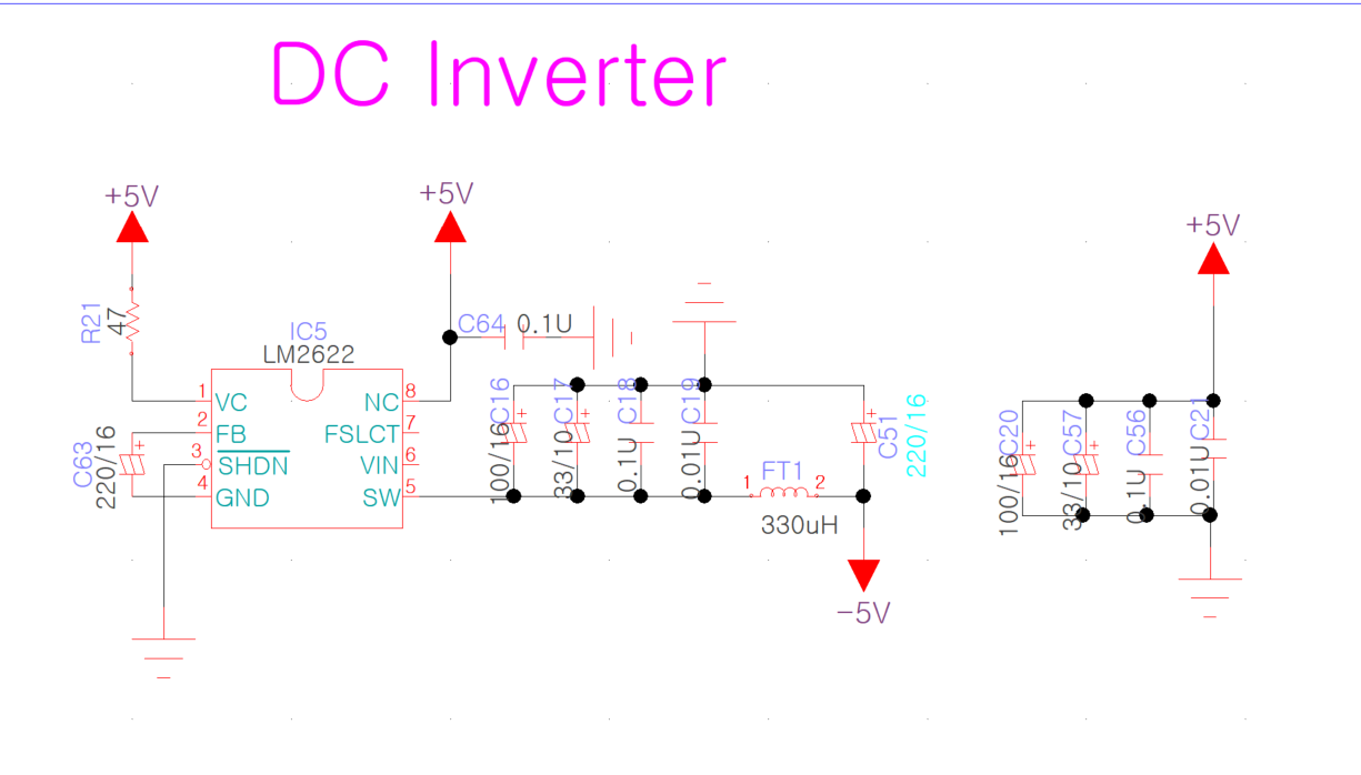
Attach the schematic file.
It is to increase the audio amplifier range. (-5Vdc ~ + 5Vdc)
Is that schematic correct?
Please, Review it.
Thank you.
Best regards,
Inho Jeon
SOVICO Professional
Hello Inho,
Thank you for using a TI product. I have 2 questions:
- The switch is internally connected from SW to GND, for an inverter you need a switch from VIN to GND. Did you get this circuit from Webench? If yes, please share the design.
- Why do you want to use especially this device? What are your current requirements. Possibly a simple charge pump like LT1054 could do the job. You could as well use TPS63700.
Dear Brigitte,
This schematic was designed by a previous developer, not me.
So, I don't know if this schematic was designed by Webench.
I just inquired to see if the LM2622 is correct for this schematic.
If not, please suggest the correct method.
Thank you.
Best Regards,
Inho Jeon
SOVICO Professional
Hi Inho,
the requirement is to generate a 5V output from -5V input, correct? if yes, the schematic is not correct.
what is the output current requirement?
Hi Inho,
Sorry I'm confused. Let me double confirm with you again, do you want to generate a negative 5V or positive 5V? Is the source +5V?
Hi Inho,
Do you want a dual output voltage of -5V and +5V?
Or just one voltage rail and its range is -5V to +5V? Is there an external signal to control the output voltage?
It would be helpful if you can tell us more details of Vin and Vout/Iout requirement.
We never used LM2622 in this kind of application. From your provided schematic, the Vin pin is open. The device could not work at all from our experience.
Dear Jack,
Attached is the schematics of the product that will be applied to the LM2622 inquired about.
This product is a device that converts several types of audio inputs into several types of outputs.
Please check and check if there are any modifications.
Thank you.
Best Regards,
Inho Jeon
SOVICO Professional
Hi Inho,
I guess it should be LM2662. Not LM2622.
LM2622 is a boost converter that converters a positive input voltage to a higher output voltage. for example, input is +3V, output voltage is +5V.
LM2662 is a charge-pump voltage converter/inverter. For ample, input voltage is +5V, output voltage is -5V.
These two devices are totally different. In your schematic, the device pin names are LM2622 pins but external passive components connection are wrong. The external passive components are very similar to LM2662. You could see LM2662 datasheet on ti.com.
Please check with engineer who designed this schematic Or check the existing board BOM file.