This thread has been locked.
If you have a related question, please click the "Ask a related question" button in the top right corner. The newly created question will be automatically linked to this question.
Hi,
I am using LM2623 and LM2622 chips for step-ups in my design.
I designed it so I will use only one of them at a time.
I have checked both of them, and I have some slightly issues with the chips.
I attached the scheme for both of them
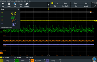
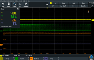
LM2622 -
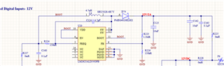
The input voltage comes from R227 and is 3.9v.
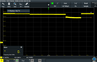
The output voltage is programmed to 12V.
The measured voltage is at R225 pad (the resistor is disconnected to prevent issues).
And on the output is connected a digital load of 400mA.
I get ripples of 800mV -
Can you verify my schematics and tell me why do i have such high ripple on so low current consumption ? the chip suppose to support a 1.2A .
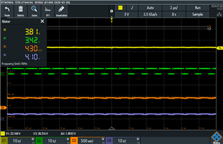
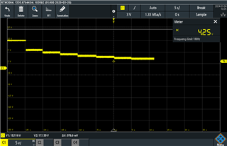
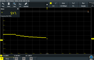
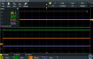
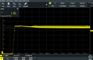
LM2623 -
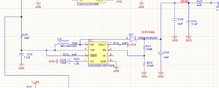
The input is the same. 3.9v. The output is measured on R228. the output load is 370mA
And i am getting those 1v ripples -
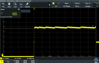
i want to ask you to verify my schematics and maybe help me with the issues above
thank you,
Michael
PS. i just saw that the pictured are not very clear. i want to attach a pdf with the schematic so it will be easier for you.
i cannot attach pdf here. if you want a pdf i will mail you the pdf
thanks
Hi Michael
I think you may have a typo in "LM2622" and "LM2623". The first schematic and waveform is LM2623 and the second one is LM2622, right?
For LM2622,
For LM2623,
Thank you.
Regards
Lei
Hi Lei, Thank you for your fast reply.
let's first solve the LM2622 and then move on to the LM2623.
I have changed the R233 and C180 according to your recommendation (24kOhm and 2.2nF)
this is the Scope picture I have taken for LM2622 with you request. I was not able to measure to current on the inductor.
Yellow - Vin
Green - SW pin (pin 5)
Brown - FB pin
Blue - Vout
no load -
1.1A load -
I also added the drop of the voltage according to the load -
starting with No load, 500mA, 600mA, 700mA.. up to 1.1A
Thanks, Michael
Adding some data for LM2623 -
Voltage degradation -
measured under - No load, 500mA,600mA,700mA... 1.1A -
why am I seeing such harsh degradation of voltage?
picture of scope - (Yellow - Vin, green - SW, brown - FB, blue - Vout)
no load -
1.1A load -
Another questions -
1. I Tried to add Tantalum capacitor to the output and input instead of ceramic. should i see any different ? or ceramic should be good enough?
2. Do you want to see the layout of the PCB ?
Thank you,
Michael.
Hi Michael,
Usually we measure the inductor like this way: lift one side of the inductor, and then connect one wire between the pads on the inductor and EVM. Following is an example.
In some of the pictures, there are more than one waveform(sun as SW voltage) shown together. You may try to zoom in and cancel zoom in immediately, then only one waveform is left and the picture will be more clean and normal.
Go back to the device of LM2622
For LM2623, it's similar that the maximum Iout is around 430mA when working from 3.9V to 12V. Bigger Iout will pull the Vout down.
Regards
Lei
Hi Lei
1. where i can find that information in data sheet that of LM2622 for output of 12V maximum Iout is around 150mA?
2. where i can find that information in data sheet that of LM2623 for output of 12V maximum Iout is around 430mA?
- Please guide me on Data Sheet, so I don't make a mistake in the future
3. In my solution, i need supply 12V to continuous solenoid that require 800mA for 2 Sec. can i do some changes on IC LM2622 or LM2623. i prefer to stay with it because I done the layout and have PCB
4. if LM2623 and LM2622 is not Suitable for my solution (solution12V to continuous 800mA). can you suggest pin to pin soliton that can supply to out 12V/800mA ?
Thank you very much for your support !! and quick response
Michael
Hi Michael,
You are welcome.
Sorry there is a small mistake in my previous calculation. The estimated maximum Iout when working from 3.9V to 12V is corrected below:
LM2622: 210mA.
LM2623A: 520mA.
Here is the way to estimate, using LM2622 as an example:
******************* Input *******************
vin = 3.9
vout = 12
L = 10/1000000
f = 600000
efficiency = 0.85
current_limit = 1
**********************************************
******************* Output ******************
D = 1-efficiency*vin/vout
DT = D/f
il_ripple = vin/L*DT
i_in_max = current_limit-il_ripple/2
i_out_max = i_in_max*vin*efficiency/vout
**********************************************
The input values come from the work conditions and datasheet.
Again let's go back to your application. Since the gap between the max Iout and the needed Iout is big, and the load during is long (~2s), to make the Vout still high enough (bigger than Vin) during the 800mA load is coming, very big Cout with capacitance around 200mF is needed. Is it acceptable?
If not, let's check whether p2p solution is available tomorrow.
BTW, could you send me the detailed load (Iout) profile? Such as after the 2s duration of 800mA, how long is the time of no load or small load?
Regards
Lei
Hi, thank you for your fast reply.
I want a temporary solution for my project until i change it to a bigger step-up.
If I change R225 and R228 in the following schematics to Diodes -
will I be able to get 730mA (summing both currents) on the output ?
Thank you,
Michael
Hi
1. what are the calculation for LM2623? i believe they are slightly different.
2. Is it possible the change the inductance in order to increase the maximum output current ? 100uH instead of 10uH can increase my current by 50mA
3. large capacitor is not a good solution to my project because I use solenoid. we switch the voltage every 10mS sometimes
thank you for your replies.
Michael
Hi Michael,
will I be able to get 730mA (summing both currents) on the output ?
This kind of solution is not recommended. Usually the total output current will less than the sum. With high probabilities only one device works at specific moment.
1. what are the calculation for LM2623? i believe they are slightly different.
You may use the following inpus
******************* Input *******************
vin = 3.9
vout = 12
L = 4.7/1000000
f = 950000
efficiency = 0.85
current_limit = 2.2
**********************************************
The output formulas are the same.
2. Is it possible the change the inductance in order to increase the maximum output current ? 100uH instead of 10uH can increase my current by 50mA
Since the gap between the max output current and the need Iout is big, it's not effective to increase the Iout by increasing the inductance.
Regards
Lei
Hi Lei, Thank you for your reply. You are very helpful
I was able to reduce my current limitation for around 500mA temporary.
I tried to load the LM2623 with 500mA and it dropped to 10.2v.
I wish to ask few last things -
1. Do you know how can I improve my design to work at 500mA ? Maybe change the Inductance ?
2. Do you know of a good solution to step-up from 3.7-3.9v to 12v with 1A?
Thank you very much for your time.
Michael
Hi Michael,
Increasing the inductance will make the max Iout a little bigger. Since you've made the work current at 500mA, the gap is not big now, you may have a try to make the inductor to 10uH.
Devices such as TPS61288 or TPS61089 can step-up from 3.7-3.9v to 12v with 1A. Does the package and size work for you?
Regards
Lei