This thread has been locked.

If you have a related question, please click the "Ask a related question" button in the top right corner. The newly created question will be automatically linked to this question.

LM5066I: Can not communicate I2C with LM5066I.

Part Number: LM5066I
Other Parts Discussed in Thread: MSP430FR5739

Hi TI expert,

Can not communicate I2C with LM5066I. 

In the link below, the LM5066I is that the default setting is SMbus. Do LM5066I have any requirements for I2C communication?

Please give me an email address if you need to check the schematic. In the circuit diagram, SCL and SDA pull up are connected to external 5V.

Thanks,

Downey Kim.

  • Hi Kim,

    Thanks for reaching out!

    Are SDAI and SDAO pins shorted together like in the EVM schematic? Which hardware are you using to interface the device? 

    Can you please check with FTDI dongle which comes with the EVM before proceeding to test with other hardware. 

    Please check the details in threads https://e2e.ti.com/support/power-management/f/196/t/757243#pi320995=1   

    https://e2e.ti.com/support/power-management/f/196/t/713532 and let me know if it helps.

    Best Regards, Rakesh

  • Hi Rakesh,

    They was using MSP430FR5739. I2C communication between MSP430FR5739 and LM5066I is not working.

    SDAI and SDAO pins shorted. 

    Please check if there are necessary conditions for I2C communication between MCU and LM5066I.

    Thanks,

    Downey Kim.

  • Hi Kim,

    To our knowledge there is no special consideration or settings needed for I2C communication with MCU.

    Best Regards, Rakesh

  • Hi, Rakesh

    The problem was solved by changing the pull up resistance value. Thanks for the help.

    I have more question.

    Use the LM5066I as a power switch. Load is an LED module. The wire length is 20~30M.

    Whenever an LED module is added, the LM5066I is protected and the power is turned off.

    FET can be turned on by changing the Cdv/dt value of the reference circuit below.

    At 10nF, power supply for LED module 1EA is possible.

    At 33nF, power supply for LED module 3EA is possible. We applied 100nF and confirmed that 6 LED modules are powered.

    When checked with an oscilloscope, there was no change in in rush current. (in rush current : 1.2~1.5A)

    1. Please tell me the applicable range of Cdv/dt capacitor values. 

    2. Do you know for some reason the protection operation is released depending on the value of the capacitor?

    Please check my questions.

    Thanks

    Downey Kim.

  • Hi Kim,

    Does the LED module adds capacitance to the output of the hot-swap ?

    Can you share the startup test waveforms (Vout, GATE, input current and timer) and test conditions when a single LED module is powered. Provide the same details for 6 LED module case also.

    Best Regards, Rakesh

  • Hi Rakesh,

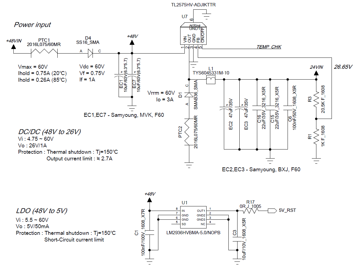
    The following 4 circuits are used per LED module. (LED module 1EA : 10uF * 2 * 4 = 10uF 8EA)

    The in rush current has not yet been caught with the scope. However, the LM5066I doesn't seem to turn on the FET by inrush current.

    When the power is on(Power on~~~), the FET does not turn off even if up to 12 LED modules are connected.

    However, with 7 LED modules connected, FET does not turn on when power is turned on(power off -> power on).

    How to increase the inrush current limit?

    Thanks,

    Downey Kim.

  • Hi Kim,

    Inrush current limit can be increased by reducing/removing the Cdvdt. 

    Are you using TI EVM for evaluation or made your own circuit with LM5066i ?

    Best Regards, Rakesh

  • Hi Rakesh,

    We made our own board. 

    Cdvdt was removed, but up to 3EA of LED module is possible. When 100nF is inserted, 8EA of LED module is possible.

    I changed the timer cap from 100nF to 680nF, but there was no improvement.

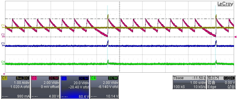
    we captured the start waveform.

    ch1 : Current.

    ch2 : Timer cap

    ch3 : gate

    ch4 : Vout

    Are there any other points that can be improved?

    Thanks,

    Downey Kim.

  • Hi Kim,

    It is mainly due to excessive load during startup. Please enable (pin-5) TL2575 from the PGOOD signal of the hot-swap. This way, the hot-swap circuit only have capacitive load during startup.

    Best Regards, Rakesh

  • Hi Rakesh,

    Thanks for your advice.

    But we can't change the circuit of the LED module. I found a FET with a high SOA 100ms current. (Nexperia : PSMN2R3-100SSE)

    when I check the calculation sheet of lm5066I, it can withstand high startup load. Could this be the solution?

    Thanks,

    Downey Kim.

  • Hi Kim,

    Yes, Stronger SOA FET will help to support higher inrush current situation during startup.

    Please test with this FET.

    Best regards, Rakesh