This thread has been locked.

If you have a related question, please click the "Ask a related question" button in the top right corner. The newly created question will be automatically linked to this question.

LM3478: Minimum current required to avoid Pulse skipping

Part Number: LM3478

Hello,

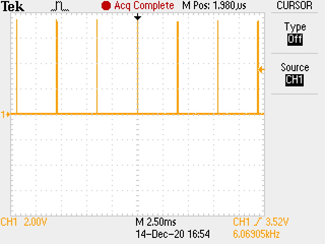
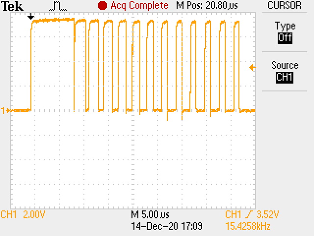
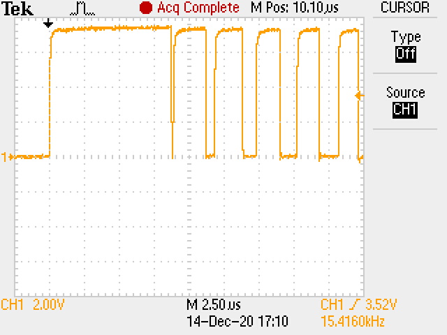
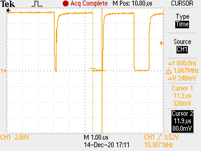
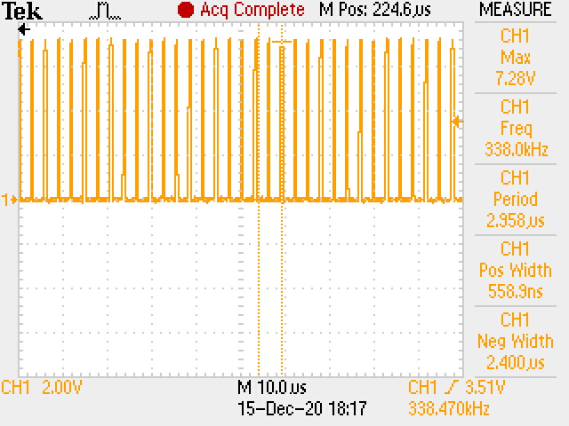
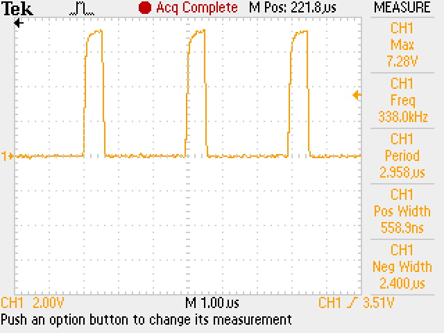
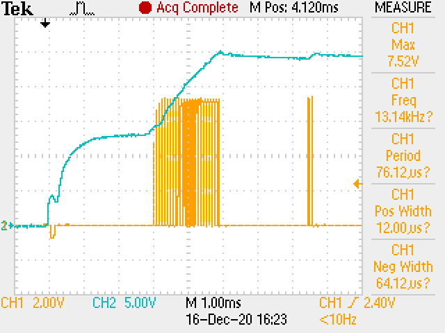
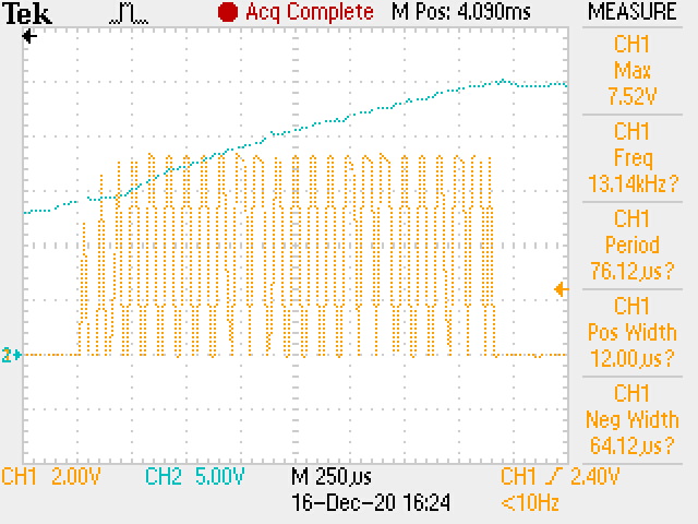
I am using the LM3478 in a 12V to 24V (5A) boost converter. The application (an audio product) is powered by a 12v SLA battery. We have had no issues until the latest production run. The problem now, is that this particular run is experiencing pulse skipping which is manifesting itself as an audible noise (objectionable) from the speaker. Upon investigation I have found the load at start-up is only about 36mA. It looks like pulse skipping is occurring. If I increase the load to, say, 60mA the problem appears to go away and I see no evidence of pulse skipping. I have looked through the datasheet and cannot find any data for this issue, only that it can occur. I have also read through other threads on the forum and only have found the equation for "Pdummy". The name implies power(the units don't seem to work out as watts), Pdummy = (1/2)*Fsw*((Vin_max*T_on_min)^2)*(Vo/(Vo-Vin_max))/Lm. So, what is the Pdummy calculation? My calculation yields 0.363; if it is power then the resistor I should use would be about 1600 ohms. With a 24V rail that means the current would be 15mA...obviously not going to solve my problem since 36mA is already causing an issue. Maybe I'm missing something here.

So my questions;

1) What is the Pdummy calculation and how can I use it to determine the "dummy load"?

2) What is the minimum current to avoid pulse skipping in my application?

3) Where can this information be found, in an app note?

Thanks for everyone's help.

Jim

  • Hi Jim,

    Thank you for using LM3478.

    Your understanding of the dummy load equation is correct. Pdummy load gives the minimum power to avoid pulse skipping. However, this is just theoretical calculation. You can check and compare the real on time at the boundary load condition. The min on time of LM3478 should fall between 210ns to 600ns per the datasheet. Do you use the 600ns as the worst case?

    I'm not sure if this is specifically specified in document but the equation itself is just a derivation from the on time at DCM and is straightforward.

    Please let me know if you have any question.

    Thanks,

    Yinsong

  • Yinsong,

    Thank you for your reply.

    I used 210nS in my calculation as I expected the smaller on time value to provide the worst case without thinking it through. With Ton_min = 600nS the calculated power is 2.96W and the dummy load resistance calculates to 194 ohms. The current is then 124mA.

    I did not realize the pulse skipping was an issue when I used Webench to calculate the values nor did I see the issue in simulation or in prototype/production. My CM has been replacing the LM3478 to solve the problem but I reckon this is not a good solution.

    Would you agree then,  that this must be the cause of my troubles since my start up current is at 36mA?

    It seems the only options I have are one of the following;

    1. Accept the behavior as it is.
    2. Add enough load to accommodate the 124mA minimum current requirement.
    3. Add enough output capacitance to filter the audible noise during pulse skipping.

    Does this assessment seem correct?

    Thanks,

    Jim

  • Hi Jim,

    The three options you listed are correct to solve the light load pulse skipping issue. 

    And yes, please use the max Ton_min for dummy load if you choose this solution.

    Please let me know if you have any question.

    Thanks,

    Yinsong

  • Yinsong,

    I appreciate all of your help with my problem so far.

    I have just realized I made an error in my current measurement (stated as 36mA) on my product. I had not included the complete system current. I have since re-measured everything and here are my results.

    The actual system start-up current is 50mA and after system soft start completes the supply current at idle increases to 100mA. Based on a maximum input voltage of 13.5 VDC and using the minimum pulse wide = 600nS I have calculated a required start up current of 109mA. This would indicate I could have a situation where the converter may pulse skip if the input voltage is 13.5VDC. However, The typical input voltage is 12.5VDC. At this input voltage the minimum load current calculates to 86mA. So with a 100mA load, I would expect the converter to operate in CCM and not pulse skip. This may explain why I have not seen a problem in production until now.

    Based on this information, I would expect the converter to start up ok but possibly pulse skip if the battery voltage was above 12.5VDC. To completely eliminate the possibility of pulse skipping, I should increase the system current to avoid pulse skipping, say to 110mA or greater. Would you agree?

    I had made changes to my circuitry to increase the current by 30mA to a total of 130mA after soft start completes. I expected that the converter would never pulse skip under this condition. But it did. I had to increase the system current to about 200mA to avoid pulse skipping altogether. This is more current than I  would like at idle since this is a battery operated product. It also seems to be higher current than expected  for the converter to avoid pulse skipping.

    Since the current increase did not completely eliminate the pulse skipping until ig doubled the system current, I am concerned that there are some parts (LM3478) that may be damaged. Does this make sense?

    Can you offer any guidance?

    Thanks,

    Jim

  • Hi Jim,

    Thanks for the detailed information.

    There are a few things you could check here.

    1. Does this issue happen on one IC/board or more?

    2. Is this 200mA boundary repeatable for steady state operation or just at start up transient. If it is the same at steady state condition, you could check the real on time of the gate at the boundary (when it just gets rid of the pulse skipping). If you can get the waveform, it would be helpful.

    Thanks,

    Yinsong

  • Yinsong,

    The behavior is affecting about 5% of each production run However, I currently have only one example on my bench so I cannot verify the point at which the controller switches to CCM on more than this single board.

    I will attempt to capture the waveform. At 200 mA load, the system seems to reliably start in CCM. I will reply with more information soon.

    Thanks,

    Jim

  • Yinsong,

    Today I am observing the system starting up and immediately going into CCM with no evidence of pulse skipping. I varied the input voltage from 10V to 14V to see if the start-up changed but the boost converter started each time with no pulse skipping. The load is about 100mA after the pwoer amplifier completes soft start.

    To attempt to capture the problem I reduced the load at start-up to about 74mA. Now the converter starts up and is in DCM, pulse skipping. I incrementally increased the load as it was running from 74mA to150mA. The converter stayed in DCM during that time as the load increased. When I increased the load to about 158mA the converter switched to CCM. 

    I have attached some scope pictures. There are 4 picture while the converter is in DCM, the first is a zoomed out shot, then 3 pictures zoomed in. All are with a 140mA load.

    The converter finally went into CCM when the load increased to 158mA

    Thanks,

    Jim

  • Hi Jim,

    Thank you for the waveforms. Do you have the CCM waveform of 158mA load as well?

    Thanks,

    Yinsong

  • Yinsong,

    Here are two waveforms when the converter is in CCM. BTW - these are the gate driver waveforms. The first is zoomed out the second one is zoomed in.

    Thanks,

    Jim

  • Yinsong,

    I have noticed a dependency on the temperature as well. I soldered near the LM3478 and afterwards the converter almost always started in DCM. If I cooled the area the converter was more likely to start in CCM.

    Here are some scope shots of the start-up that resulting in DCM. This is with the system in its "as designed" configuration where the initial load is about 50mA and then 100mA after the power amplifier comes out of soft start. Channel 1 is the gate drive and channel 2 is the 24V output.

    Thanks, Jim

  • Hi Jim,

    It looks like the 558.9ns pulse width is within the 600ns spec. I guess the mismatch just come from the calculation error from the equation, including the component tolerance, etc. In this case, I think you will just need to see if the 200mA dummy load is acceptable to you or not.

    Thanks,

    Yinsong

  • Yisong,

    Thank you for your assistance. I have come to the same conclusion so it is good to have your expert opinion as well.

    Best regards,

    Jim