This thread has been locked.

If you have a related question, please click the "Ask a related question" button in the top right corner. The newly created question will be automatically linked to this question.

BQ24070: BQ24070

Part Number: BQ24070

Hi,

I am using one BQ24070 as a Power path manage IC for my battery charging and regulated power for 2G modem. (as shown in the below picture)

When the Mosfet switch turns ON, a glitch comes in the regulated output of BQ24070.

Please help to understand the reason for this glitch as the output rating of BQ24070 is within the limit. (continuous drawn current is maxed 700mA and surge is 1.6A from Modem which again compensated by using tantalum capacitor close to Modem.)

I am suspecting some wrong configuration of BQ24070. Please help to review it for this application.

Note: This glitch comes only when the battery is disconnected. Once the charged Battery is connected, it works fine.

  • Hi Mr. Gupta,

    I am unable to see the images correctly. can you try to re-upload? Also it would be great if you have schematics/ waveforms. 

    Regards,

    Gautham

  • Hi Gautham

    Please see attached file for your reference.

    6175.TI_Query.pdf

  • Hi,

    It looks like this glitch would be due to the 470uF cap charging with the MOSFET switch being turned on. The cap is pulling a high amount of current that is causing the output to drop until it becomes fully charged. This can cause the output to drop temporarily as the capacitor becomes charged. With the battery, the device is able to utilize its battery supplement to maintain the voltage on the output and is why you don't see the drop when the battery is attached.

    With the schematic, this problem may be reduced with capacitors (0.1uF minimum) that are required on the IN and OUT pin. We also recommend a 33uF capacitor on the BAT pin for operation when battery is not attached. 

  • Hi Anthony,

    Thanks for the valuable feedback.

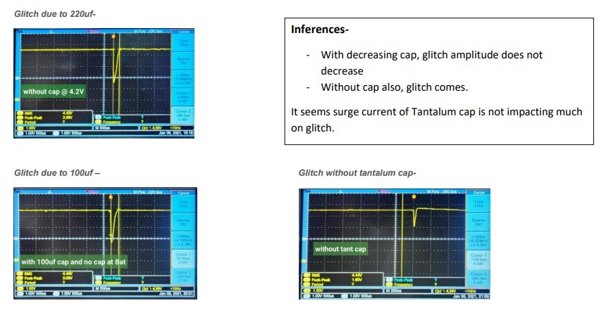
    As per your suggestions, we did a debugging session whose results are as per below-


    - It looks like this glitch would be due to the 470uF cap charging with the MOSFET switch being turned on.

    We reduced cap value and removed cap to check surge impact, but it seems it's not impacting much.


    With the schematic, this problem may be reduced with capacitors (0.1uF minimum) that are required on the IN and OUT pin.

    - We have tried 0.1uf along with 10uf at input and output of Battery charger. But it is not impacting much on the glitch.


    We also recommend a 33uF capacitor on the BAT pin for operation when the battery is not attached. 

    - We tried with 33uf cap at BAT pin. But it is not impacting any glitch amplitude but increases the charging slope.

    For your reference, all debugging snapshots have been attached in the attachment.

    We would really thankful if you can provide more inputs on this issue.PGupta Comments on TI Suggestions.pdf


  • Hi, 

    Can you also provide a voltage waveform at the input? The waveforms you've provided for the 220uF (which you mention the 470uF was miswritten), indicate that that the tantalum capacitor is increasing the glitch is that correct?

    Is there a specific reason for still including the tantalum cap even with these results? What happens if you add the capacitor on top of this (increase capacitor at output to 470uF and remove tantalum cap). 

  • Hi Anthony

    Can you also provide a voltage waveform at the input?-

    We already checked the input of BQ24070 and did not find any glitch in power. For your reference, we will capture it again and share it with you.

    indicate that that the tantalum capacitor is increasing the glitch is that correct?-

    Correct, it increasing its glitch amplitude. But to be very clear, this glitch also comes without any bulk tantlum cap.

    Is there a specific reason for still including the tantalum cap even with these results?

    Yes. This Battery charger output is fed to 2G Modem, which has peak current requirement for some 700us. So with these tantlum caps we are compensating for peak current requirement.  

    What happens if you add the capacitor on top of this (increase capacitor at output to 470uF and remove tantalum cap). 

    We will test this scenario.


  • Hi,

    Thank you for the reply and information, I will await your test results. I appreciate the communication.