This thread has been locked.

If you have a related question, please click the "Ask a related question" button in the top right corner. The newly created question will be automatically linked to this question.

TL1431: unstable output (oscillation) No.2

Part Number: TL1431
Other Parts Discussed in Thread: TL431,

Hi support team.

I have additional questions about the following posts in the past.
e2e.ti.com/.../3579898

Would you please support me in this issue again?

I would like to ask three questions below.

1. Is it safe to assume that increasing the output capacitor will improve stability?
2. It was found that the load current of 80mA is present.
 Is Figure 12 in the data sheet measured under no load?
  Even if there is a load, is there any problem if I judge by the value of IKA?

3. Do you have data that simulates stability with Spice?

I would appreciate it if you could answer my questions.
Let me know if you have any questions.

Thank you for your cooperation.

Best regards,
Higa

  • Hi Higa,

    What is the current capacitor being used?

    1. Increasing the capacitor can make the device more stable if the capacitor is larger than several uF. But this comes with added size and slower speed. If this is ok then please increase the capacitor value.

    2. Please design for the worst case condition. Is the load always on? If the load is always on then you can design for higher IKA and use smaller capacitors. The situation I want to avoid is designing with small capacitors for high IKA then the system has low IKA and the oscillations can damage the load.

    3. We do not have a spice model for this device that shows stability region.

  • Hi Marcoo-san

    Thank you for your reply.

    My customer is using 10uF ceramic capacitor.

    1. -> What is the "size" you mentioned?

    2. -> The load is not always on.

      The load is increasing or decreasing, up to 80mA.

    3. -> OK. I see.

    Best regards,

    Higa

  • Hi Higa,

    1. The 10uF is good.

    2. Does this mean the TL431 is biased to handle 80mA worst case? What is the output voltage? There might be thermal concerns.

  • Hi Marcoo-san

    Thank you for your support.

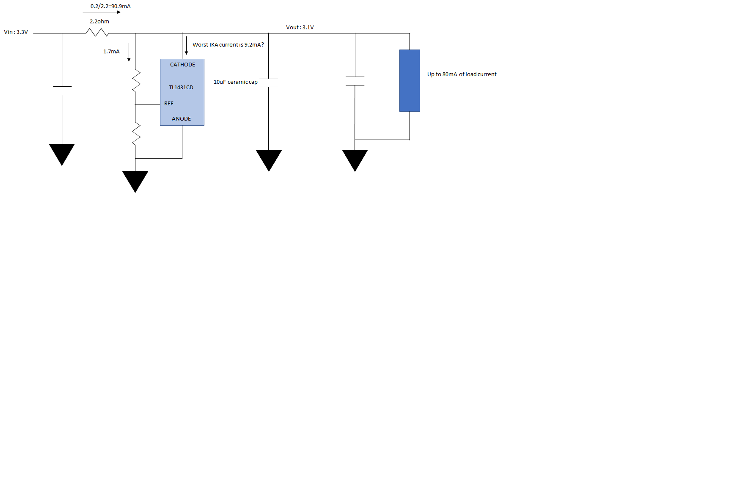
    Could you please review the following circuit?

    Best regards,

    Higa


  • Hi Daisuke,

    Is there a reason they want to use a TL1431 in this configuration over an LDO or discrete LDO with TL1431 due to such a high output current?

    The worst case current so when the load is off so the TL431 will take close to 90mA of current.

    The theta JA of the TL1431 is 114.7. 3.3V * 90mA = 279mW. Which is a 32C increase.

    The schematic looks good to me, just make sure that they can handle a 32C power increase just in case they operate at high temperature.

  • Hi Marcoo-san

    Thank you for your kind support.

    My customer has already used it and I don't know why.

    I received additional question from my customer.

    How many samples did the FIG12 data in the data sheet come from?

    Best regards,

    Higa  

  • Hi Higa,

    Sadly I do not know how many units it took. That figure was created over 20-30 years ago.

  • Hi Marcoo-san

    Thank you for your reply

    OK. I understood.

    Sincerely,

    Higa