This thread has been locked.

If you have a related question, please click the "Ask a related question" button in the top right corner. The newly created question will be automatically linked to this question.

UCC256304: Schematic design review for the dual output power supply using UCC256304

Part Number: UCC256304
Other Parts Discussed in Thread: TLV431

Hello,

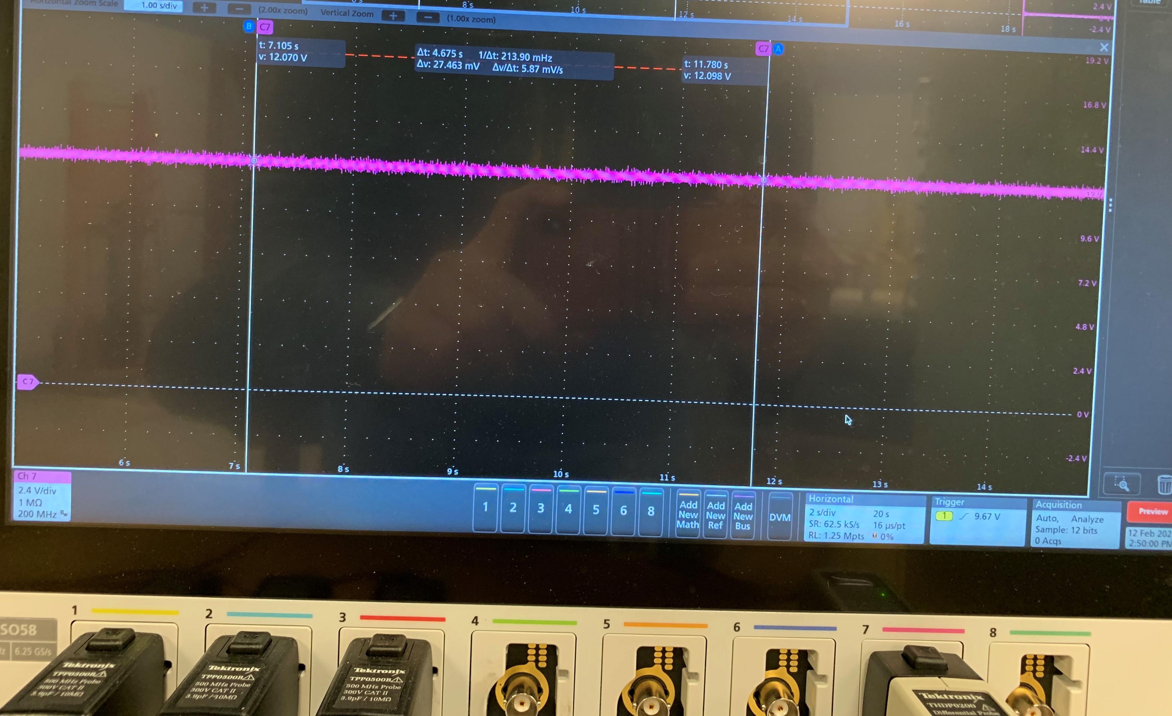
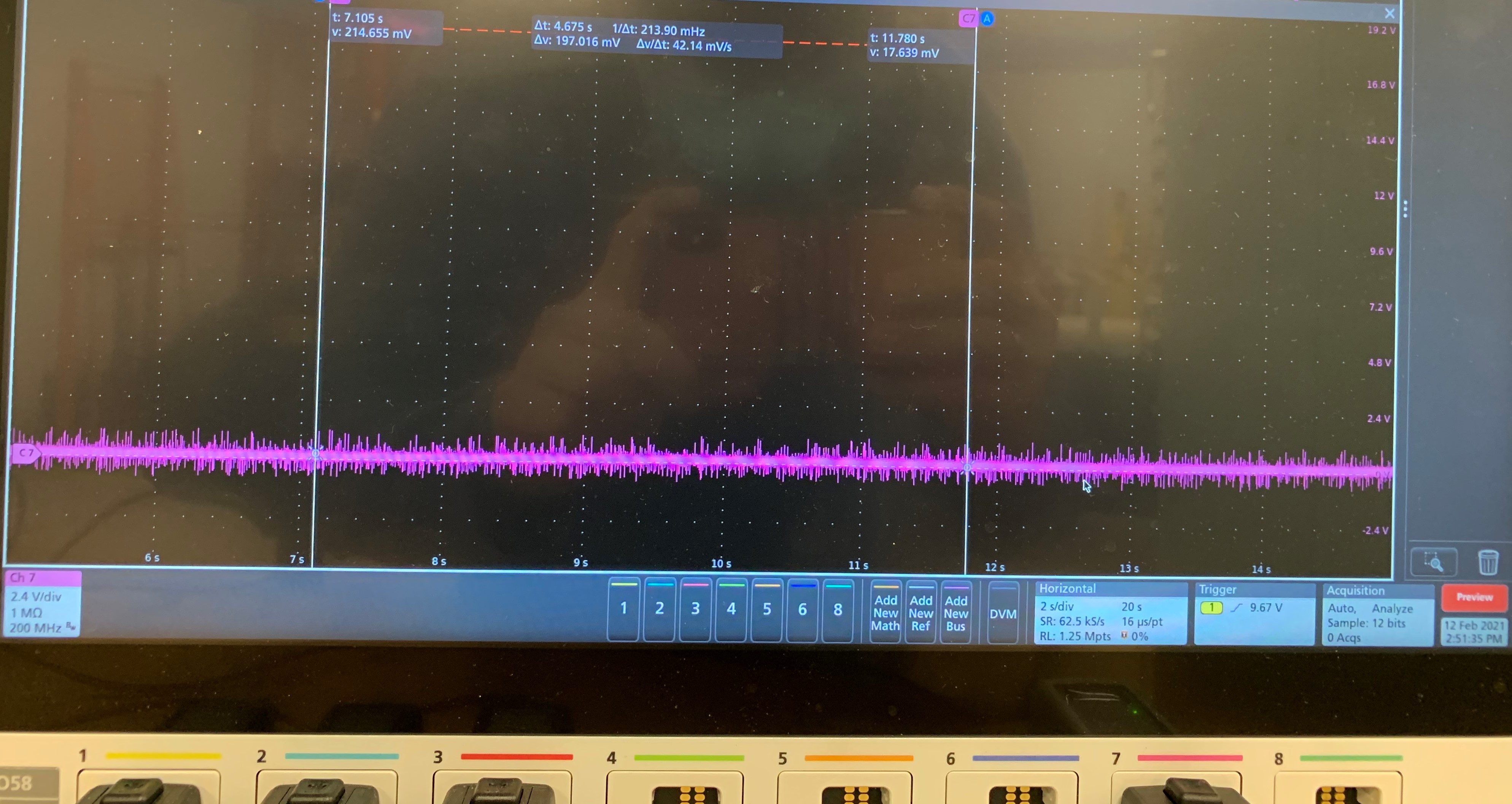
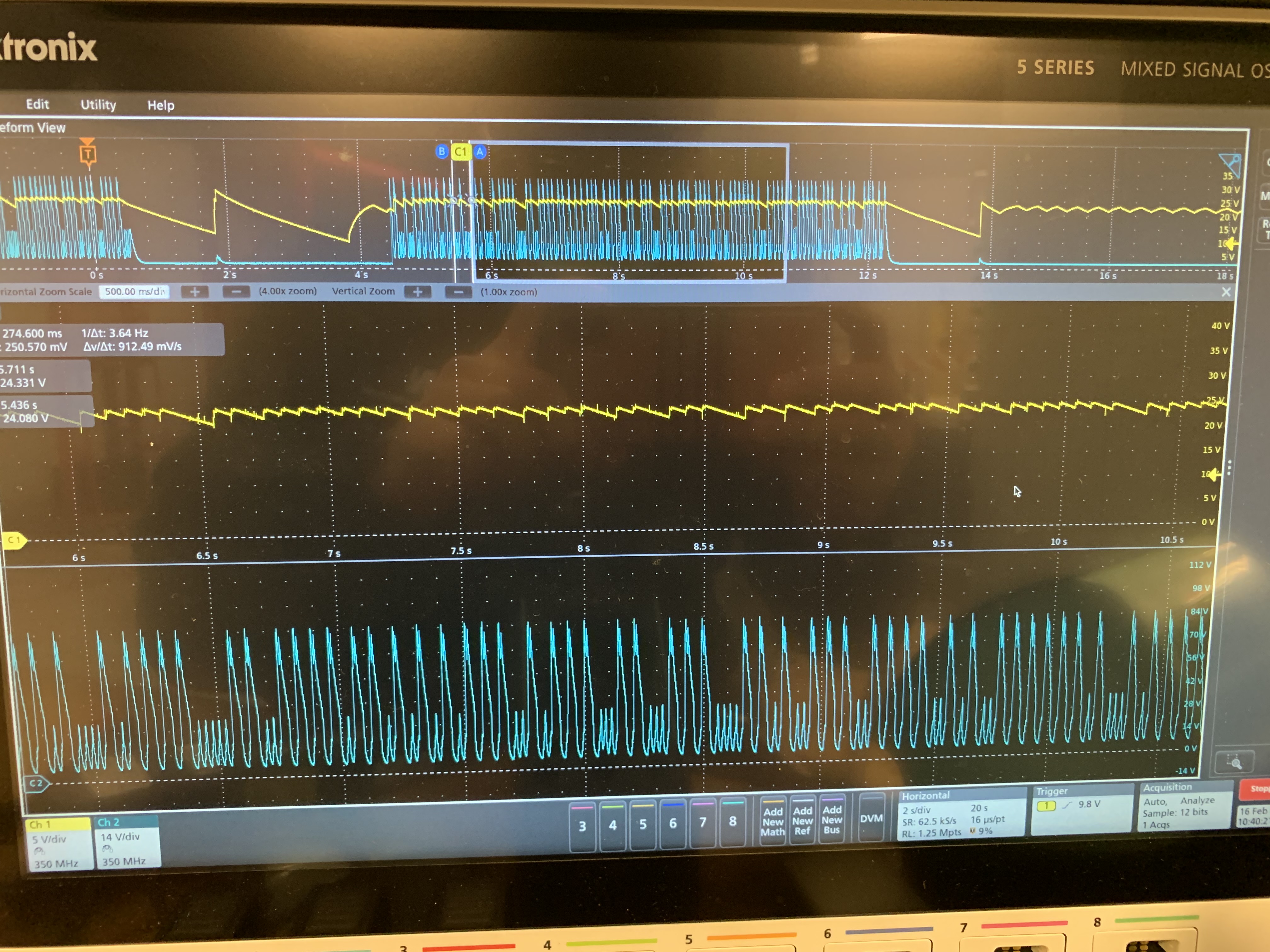
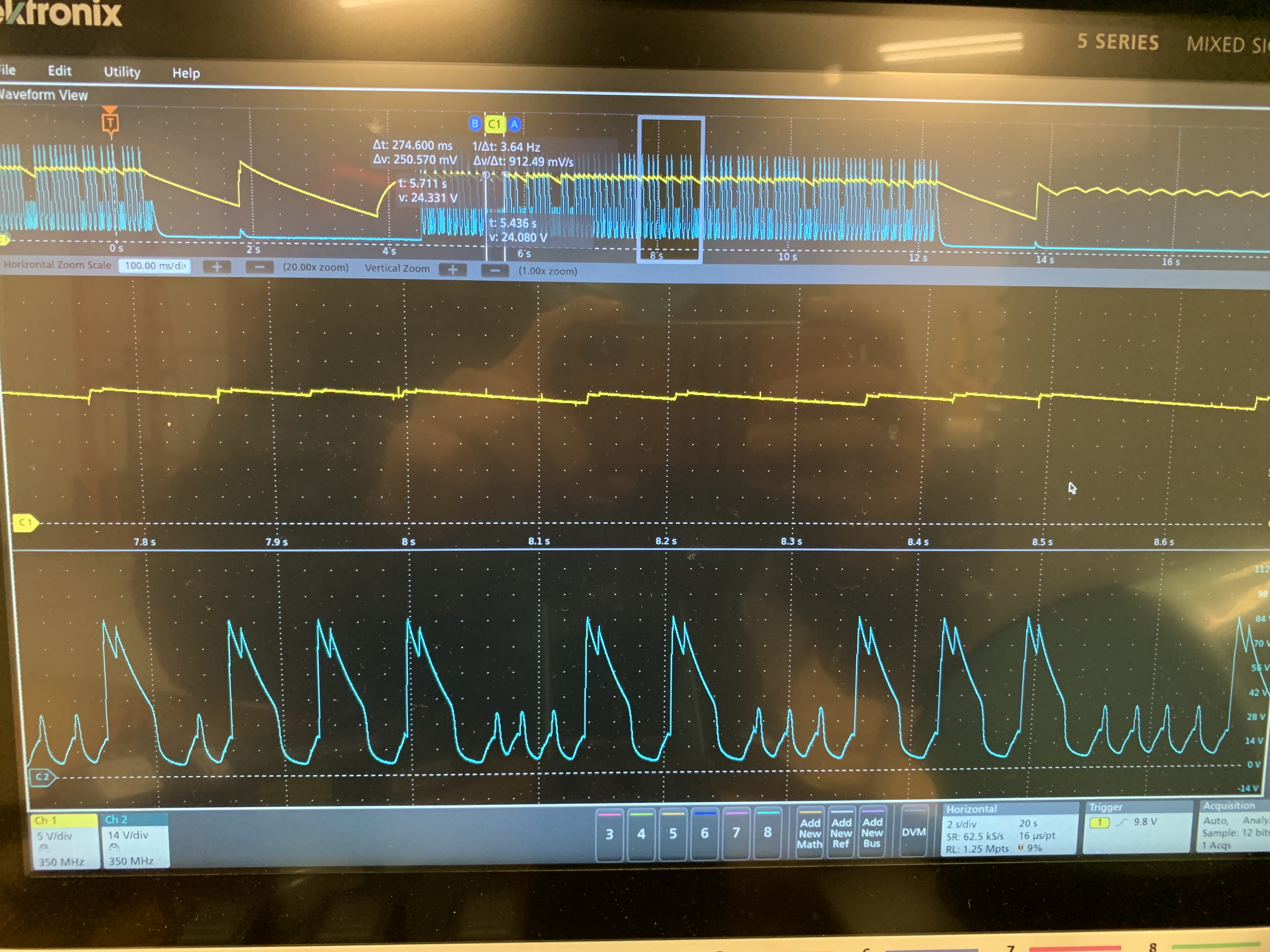
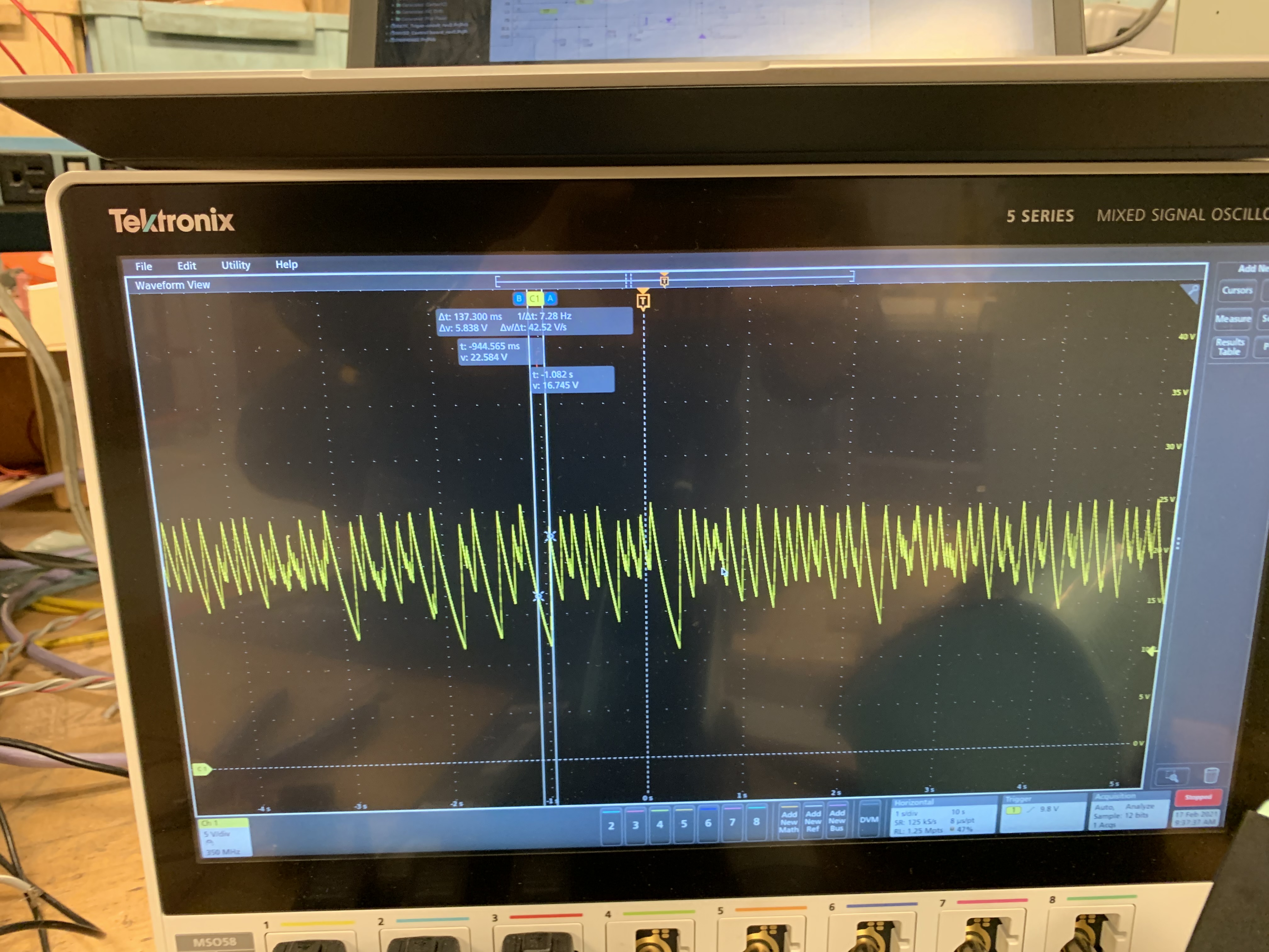
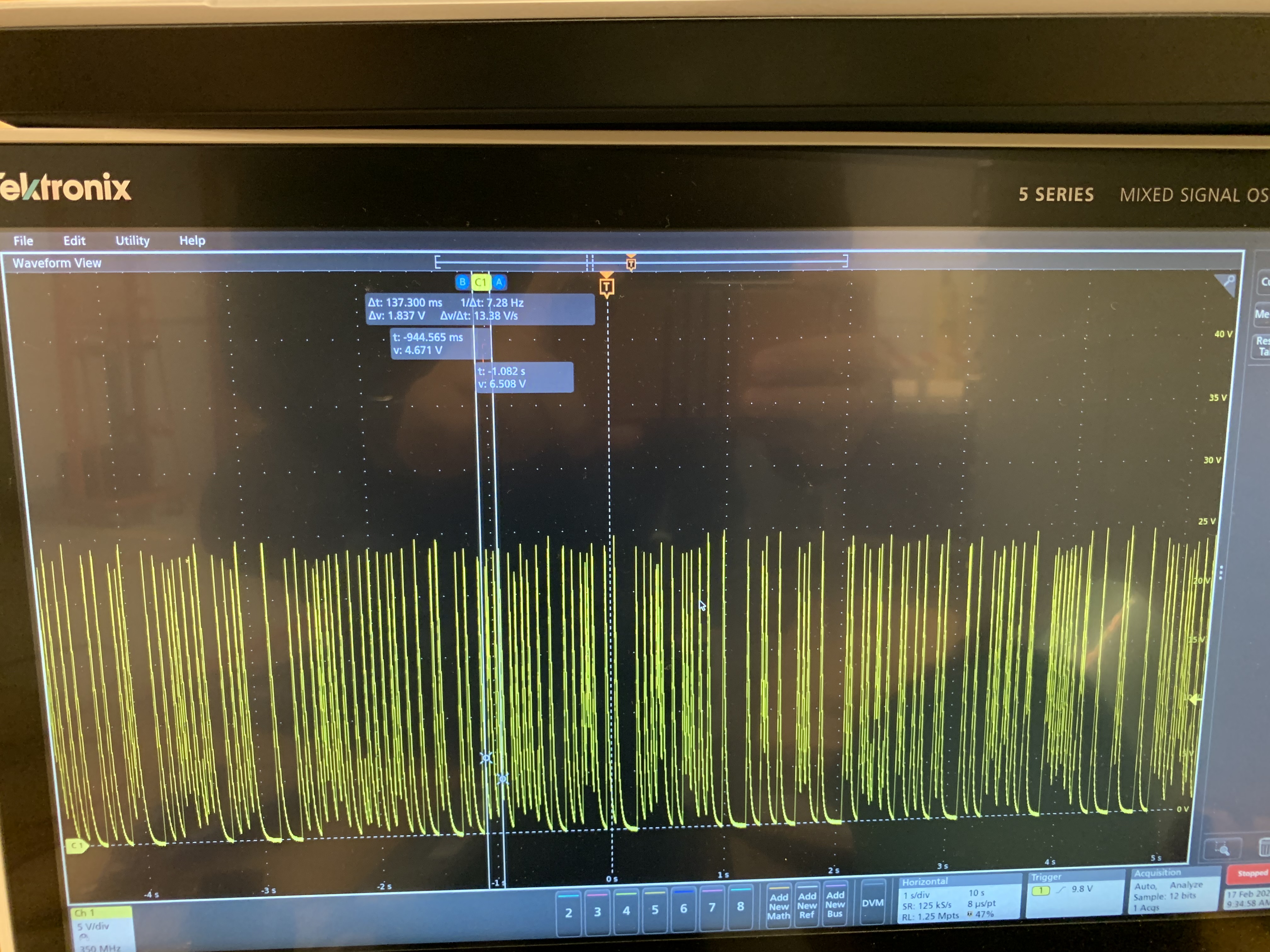
Attached is the schematic for the power supply I have designed using UCC256304. I am getting 24V and 90V as output at no load but as soon as I connect resistive load to 24V output, it is acting weirdly and I am getting random pulses of 24V magnitude. Please see the attached photo of 24V output with 100Ohm load. Please help!

Thanks4370.Power Supply.pdf ,

Dhruv

  • Hi Dhruv,

    Could you try loading the 90V rail? It looks like the LLC is in burst mode. Because the FB loop is only looking at the 90V rail, the feedback loop won't be able to see the 24V has dropped out. Try loading down the 90V rail enough to get out of burst mode. You can also consider doing weighted feedback so that both 24V and 90V are connected to the feedback divider.

    Best Regards,

    Ben Lough

  • Hello Ben,

    Thanks for reply.

    Here is the output when I attached 50Ohm resistor to the 90V rail. Yellow (top) curve is of 24V output and blue(Bottom)curve is of 90V. I can see the voltage is going higher then the designed value in pulses, 30V for 24V output and 105V for 90V output. Is there any example of weighted feedback you can provide. I am not sure how to do that.

    Thanks again,

    Dhruv

  • Hi Dhruv,

    Could you share a waveform of RVCC, ISNS, VCR and BW? Based on the switching pattern, the controller may be detecting a fault and shutting off.

    Best Regards,

    Ben Lough

  • Ben,

    Do you want waveform when the load is applied? Is waveform at no load condition will work? It is difficult to probe those signal on board for me so asking this.

    Thanks,

    Dhruv

  • Ben,

    Voltage at the pins:

    At RVCC = 12V

    At VCR = 3V

    At ISNS = 0V

    At BW = 0V

    I am workiing on to get the waveform.

    Thanks,

    Dhruv

  • Hi Dhruv,

    Please share waveforms both when the load is applied and when no load is applied.

    Best Regards,

    Ben Lough

  • Hello Ben,

    So whenever I try to connect the oscilloscope probe gnd to the power gnd on board plot signals you mentioned it is shorting somewhere and giving big spark at that point on board , the fuse at input also gets blow out. I tried few times and result was same. Do you know why it is happening?

    Thanks,

    Dhruv

  • Hi Dhruv,

    Are you using an isolated AC source to power the board? Is your oscilloscope hard-tied to earth gnd?

    Best Regards,

    Ben Lough

  • Good morning Ben!

    No, I am not using isolated AC source to power the board, it is directly powered from the wall socket. I am using 3 pin plug with earth gand to power up the oscilloscope so I guess it is tied to earth gnd.

    Thanks,

    Dhruv

  • Hi Dhruv,

    This can be quite dangerous dangerous. Do you have an isolated AC source available to you? Or an isolated 1:1 AC transformer? The primary gnd is going to be a diode drop away from either L or N. When you connect to the scope gnd, it may be connecting earth gnd directly to a diode drop away from L or N and this is causing a spark when the probe touches.

    Best Regards,

    Ben Lough

  • Ben,

    Yes, I think now I know how dangerous it is!! Yes, I do have 1:1 transformer with me that I can use but the earth terminal is not isolated. Will that work?  I was looking for reason on why it happened and found out the using differential prob also solves the problem as differential prob also have floating ground and not connected to Earth. Do you think by isolating board with transformer and using differential prob will solve this spark problem?

    Thanks,

    Dhruv

  • Hi Dhruv,

    Yes, using differential probes would avoid the sparking issue because of the floating gnd.

    Best Regards,

    Ben Lough

  • Hello Ben,

    Finally I was able to measure all the voltage waveform safely!

    Here are the waveforms:

    1. At No Load:

    a. RVCC

    B. ISNS

    C. VCR

    D. BW

    2. At Load 1k resistor:

    A. RVCC

    B. ISNS

    C. VCR

    D. BW

    3. At Load 100Ohm resistor

    A. RVCC

    B. ISNS

    C. VCR

    D. BW

    Let me know what you think about it.

    Thanks,

    Dhruv

  • Hi Dhruv,

    Thanks for the waveforms. The BW waveform with the 1kΩ load resistance looks like it could be going above the 4V protection threshold. As an experiment, could you try depopulating R11 and see if the LLC continues to attempt to restart every ~1s?

    Best Regards,

    Ben Lough

  • Hello Ben,

    Thanks for reply.

    I depopulate the Resistor R11, but LLC is still attempting to restart after every ~1s. Here is BW waveform after taking R11 out.

    Thanks,

    Dhruv

  • Hi Dhruv,

    With R11 depopulated the BW pin should only have the 10kΩ resistor to gnd and a bypass cap but your waveform shows there is still significant voltage on the pin. Is the BW pin connected to anything else in your layout that is perhaps not represented on the schematic? 

    Reviewing your schematic again, could you confirm the turns ratio between NP1 and NP2? The schematic lists NP1:NP2 = 1:5.67 but this would mean the AUX winding will have a very large voltage. Are these numbers flipped?

    Best Regards,

    Ben Lough

  • No, BW pin is connected to C23, R11 and R12 only in layout also. I am going to do same thing with another board and will let you know how that board acts.

    Yes, those numbers are flipped. Sorry for that. The actual turns ratio is : Np1: Np2: Ns1: Ns2 = 1: 0.1763 : 1.06 : 0.2941.

    Thanks,

    Dhruv

  • Hi Dhruv,

    Thanks for the confirmation. the 1s fault is normally either OCP (ISNS) or OVP (BW). Perhaps the spike in the BW waveform with R11 depopulated is switching noise coupling into the probe. If you continue to see the 1s restart, then try decrease the value of RISNS to be smaller. Another item to check is to confirm BLK is staying above the 0.87V stop threshold. I don't suspect this based on the values in the schematic but it would be good to rule this out. 

    Best Regards,

    Ben Lough

  • Hello Ben,

    I replaces Risns with smaller value of resistors (200, 150 Ohms) but still I am getting restart after 1s. The voltage at BLK is higher than 0.87V. It is 1.26V at BLK pin. 

    Thanks,

    Dhruv

  • Hi Dhruv,

    Please try reducing down to 50Ω for the ISNS resistance and change Cvcrlower to 5.6nF. 

    Best Regards,

    Ben Lough

  • Hello Ben, 

    Yes, I will do that and will let you know the results.

    I made few changes to circuit and now the output is not restarting after 1s but it is giving unusual output. 

    I increased value of C22 to 1.5uF and C28 to 150nF. Also the Risns is 200Ohm and R11 is not in circuit. Here is my output.

    It gave ~90V and ~24V for few seconds and then it turned to above given pulses. Let me know what you thtink about it.

    Thanks,

    Dhruv

  • Hi Dhruv,

    Looks like a stability issue. Could you try changing R18 to 100kΩ and R14 to 10kΩ and let me know if the behavior improves?

    Best Regards,

    Ben Lough

  • Hello Ben,

    So after making R18 of 100kOhm and R14 of 10kOhm it looks like it solved most of the issues. Here is the output after the modification.

    The 90V output is giving ~85V. Do you know why it is happening? Also what value of R11 should I use?

    Thanks,

    Dhruv

  • Hi Dhruv,

    Glad to hear the the behavior is improved. It may just be the FB divider needs fine tuned to get a precise 90V. Try dropping R17 to 7.87kΩ.

    For R11, try to target the trip point to be ~130% to 150% of nominal output voltage. I think this should be enough to avoid nuisance tripping OVP during normal operation.

    Best Regards,

    Ben Lough

  • Hello Ben,

    I have tried reducing R17 to 7.87kOhm now and I did the same thing before also but there is no change in output voltage.

    Thanks,

    Dhruv

  • Hi Dhruv,

    Check the voltage at the REF pin on the TLV431 and see if it aligns with the reference voltage. If it does not, check the voltage on VCR and see if the peak to peak voltage of VCR is 6V.

    Best Regards,

    Ben Lough

  • Hello Ben,

    So when no load is connected, the voltage at 90V rail is ~91V and voltage at REF pin of TLV431 is 1.28V which is out of the reference voltage range. But when I apply the load of 50Ohm to 90V rail, the voltage drops to 83V and the REF pin voltage also drops to 1.1V. Here is the VCR voltage waveform at 50Ohm load at 90V rail. (Pink is VCR, Blue is 90V rail and Yellow is 24V rail)

    Also when I just applied load at 24V rail then the output was not constant 24V. The voltage at 90V rail was ~90V when load is just at 24V and the REF pin voltage was 1.28V. See the 24V output voltage below.

    1. At 1kOhm

    2. At 50Ohm

    Let me know what you think on this.

    Thanks,

    Dhruv

  • Hi Dhruv,

    Try looking at the REF pin and cathode pin at the same time. The expectation is that when REF is higher than the reference voltage, the TLV431 should attempt to sink more current and therefore the voltage on the cathode should be lower. When REF is lower than the reference voltage, the TLV431 should sink very little current and the cathode voltage should float up close to 11V in this case.

    Right now the 24V is not fed into the feedback loop at all, the control loop won't see it. I would suggest to try weighted feedback where both outputs are fed into the FB divider.

    Best Regards,

    Ben Lough

  • Hello Ben,

    The no-load condition: Cathode voltage = 1.02V, REF voltage = 1.28V and output = 91V/24V

    At 50Ohm load in 90V rail = Cathode voltage = 3.65V, REF voltage = 1.05V and output = 83V/24V

    Please let me know if you figure what is going wrong here.

    I will implement weighted feedback loop for next rev to make 24 rail in control. Any recommendation on how to select weight for the output rails?

    Thanks,

    Dhruv 

  • Hi Dhruv,

    I would suggest double checking the exact TLV431 version you have and make sure the cathode pin of the device is the cathode connection in the layout and the REF pin of the device is the REF connection in the layout. It sounds like REF and Cathode are flipped. Also try installing a fresh TLV431 and see if the behavior is the same.

    Assuming your output voltage tolerance requirements are similar between the two rails, I would suggest giving preference to the higher power rail to be the "weightier" of the two outputs in the feedback loop.

    Best Regards,

    Ben Lough

  • Hello Ben,

    I double check my connection for the TLV431 IC and seems to be correct, I will replace it with a new ic and will let you know if that makes any difference.

    Thanks,

    Dhruv

  • Hi Dhruv,

    You may want to check where your feedback divider is located in the layout and measure the output voltage directly at the top of the FB divider. Another possible reason for the droop is that the FB divider is looking at a different place in the physical layout than where the output voltage measurement is taking place. 

    Is the VCR peak to peak voltage at or near 6V when you apply the load? If yes, I would suggest to increase the capacitance of the VCR lower cap.

    Best Regards,

    Ben Lough

  • Hello Ben,

    So after changing the TLV431 IC, now the voltage staying stable ~90V with the proper Reference voltage at REF pin, the output works fine with resistive load and giving smooth output voltage but when I applied 90V DC motor to it. It again started turning on and off at around 1s interval. Here is the output voltage when 90V motor is applied to it.

    Blue is 90V rail and yellow is 24V rail. Let me know what you think.

    Thanks,

    Dhruv

  • Hi Dhruv,

    Glad to hear a new TLV431 resolved the original regulation issue. Do you know what is the load the DC motor is drawing from the 90V rail? Some motors will demand a very large initial current to get turning. This may be causing the controller to trip OCP or OVP. Can you check RVCC with the motor load? If RVCC is enabling/disabling every 1s, then it is one of these faults.

    Best Regards,

    Ben Lough

  • Hello Ben,

    I am not very sure how much load it is drawing from the 90V rail, but there is no load applied to motor. It is connected to a gear so there is some friction but I guess it is drawing few hundreds of mA. I will measure and let you know how much it is drawing. 

    Also, for the board I am testing here does not have  Rllupper and R11 so I think it is not looking for OCP and OVP. Correct me if I am wrong here. I check RVCC voltage now. Let me know if you think there can be issue with anything else.

    Thanks,

    Dhruv

  • Hi Dhruv,

    The absence of R11 will prevent OVP tripping but OCP is still possible. Rllupper is part of the burst mode programming and shouldn't impact either OCP or OVP. 

    In this case, I would suggest confirming RVCC is disabling every 1s. If yes, try reducing Cisns or Risns.

    Best Regards,

    Ben Lough

  • Hello Ben,

    Ah, yes I confused ISNS pin with LL/SS pin. Thanks for explanation. 

    Yes, RVCC is getting disabled every second. Here is the waveform of RVCC on motor load.

    Blue waveform is 90V rail and pink is RVCC waveform. It is aligned with 90V rail and restarting after 1s. 

    I tried to lower Risns value to 120Ohm but output is still same. Do you think I should go lower?

    Thanks,

    Dhruv

  • Hi Dhruv,

    Are you able to deliver full load power for the 90V rail with a fixed, non-motor, load? 

    I think it is worthwhile to try a smaller Risns value. 

    Best Regards,

    Ben Lough

  • Hello Ben,

    Does the UCC256304 controller will work if I take the Risns out from the circuit?

    Thanks,

    Dhurv

  • Hi Dhruv,

    Please keep the resistor in. The controller looks at the ISNS polarity at every gate falling edge for ZCS protection. This function will not work properly if the ISNS circuitry is removed entirely.

    Best Regards,

    Ben Lough