Because of the holidays, TI E2E™ design support forum responses will be delayed from Dec. 25 through Jan. 2. Thank you for your patience.

This thread has been locked.

If you have a related question, please click the "Ask a related question" button in the top right corner. The newly created question will be automatically linked to this question.

LM5023: LM5023 using issues

Part Number: LM5023

Hi TI expert

We have two issues while using LM5023. Please help to check.

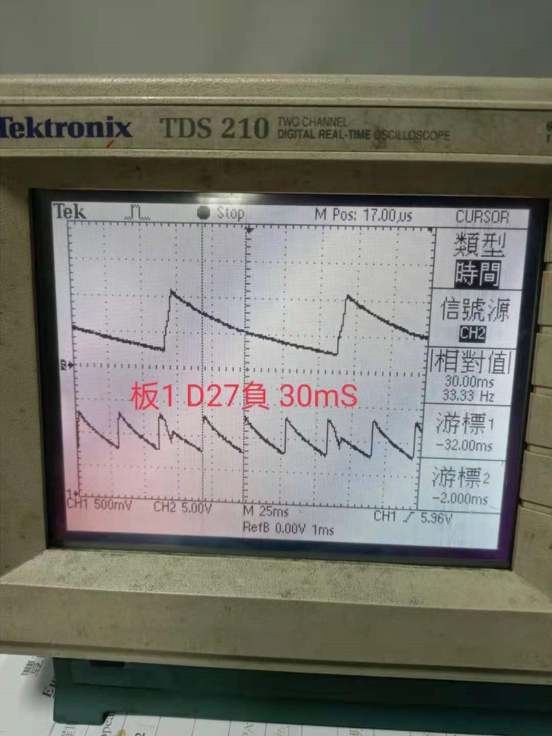
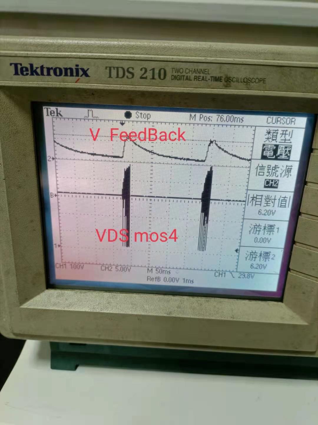
1. The output of VCC is always overloaded. Please refer as attached screenshot.

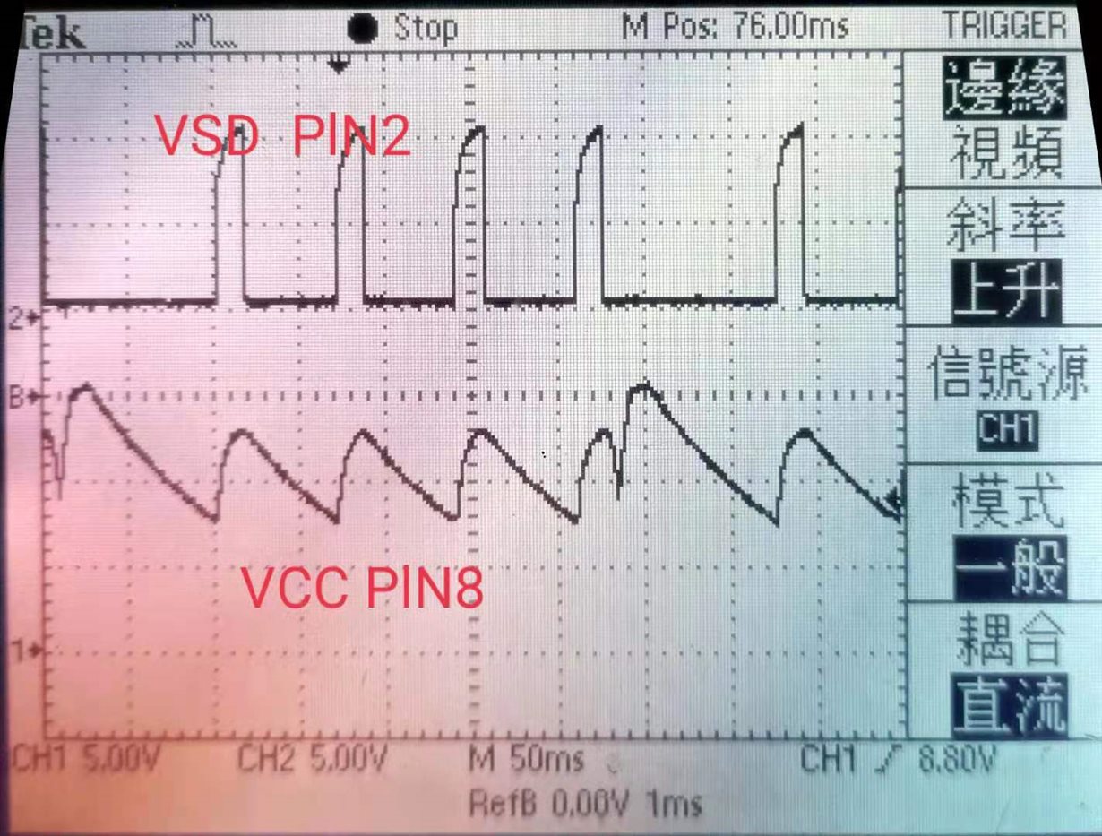
2. VCC (pin 8) will maintain 15 V pin 2 wave and VCC will not drop to zero.

Best regards,

Thomas

  • Hi, Li

    Could you help to provide schematic to analysis this issue? It is better to have components value on the schematic.

    Yunsheng

  • Hi Yunsheng

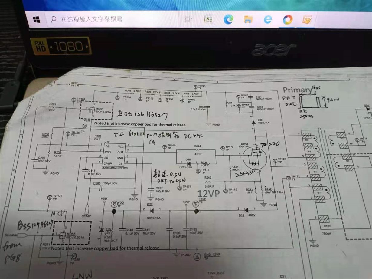
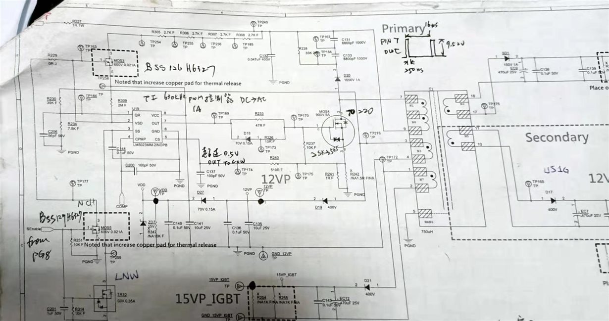
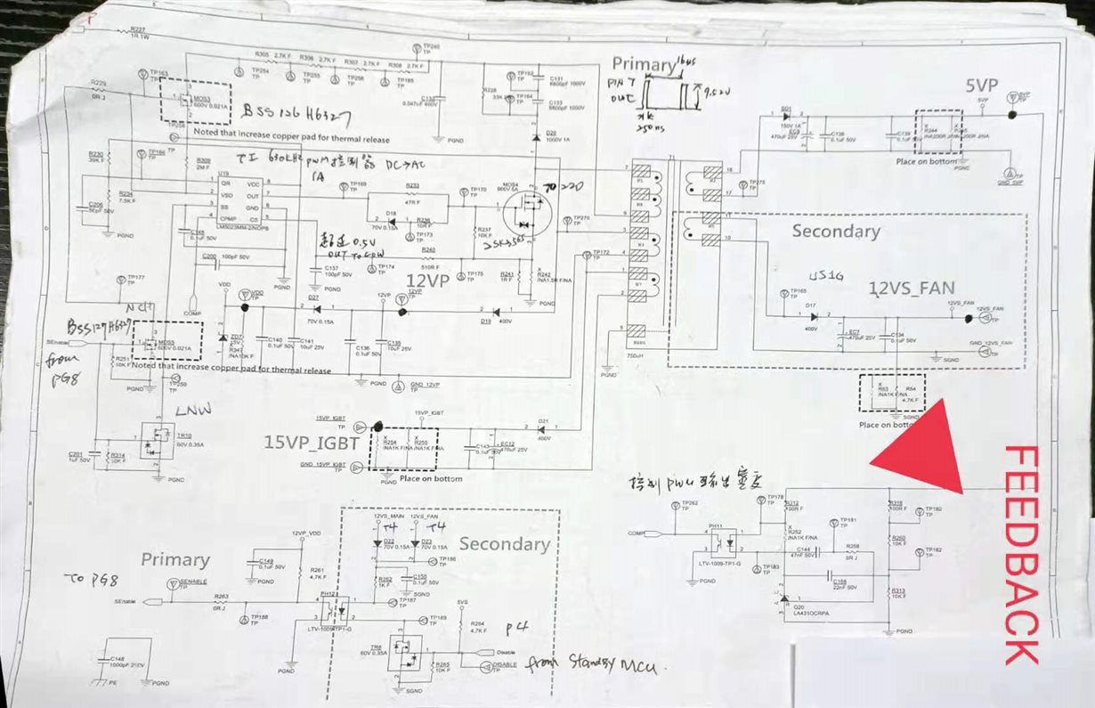
     Pls look the attached schematic screenshot , it shows our circuit structure and components , the next picture shows our problem

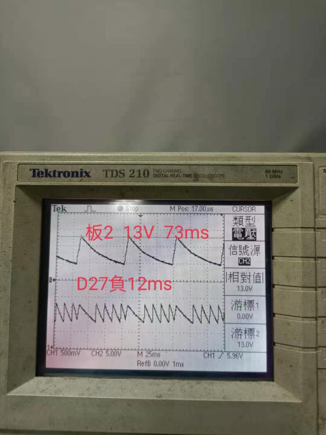
    “Vcc can not keep stable at 12v” , it always showing a overload situation on the Vcc lead(trace1 on the picture ---measured from d27 - ) , but we are not able to see where is the problem, you also can see the output curve on the transformer output d27 + (trace 2—the top trace, out put peak 13v) ,

     Pls tell us what may be the root cause

    Thank you

  • Hello, Li Chen,

    Could you please share a complete and more clear schematic .

    1. what is your transformer turn ratios (each output ) and Lm ,

    2. What is the input voltage and output voltage/load of each channel when you find the issue happens ?

    3. Please capture the VDD voltage, Vout (feedback path) , Mosfet Vds . in the same waveform.

    4. Even you have told us that trace 1 is VDD voltage , but I still don't know which one is trace 1 . upside one or down side one . since the scale of CH1 is 500mV .

    Thanks.

  • Hi Jaden Ning

     Pls check the attached picture , it shows vsd  and vcc , second attachment is the schematic, (tr10 and r229 is not connected)

     Transformer  : n1 : 47 turns  , n2 : 4 turns ,n3: 9 turns   , n5 : 9 turns , n7 : 10 turns , n6: 41 turns

  • Hi Li Chen,

    Please find my reply in attachment. Thanks.

    LM5023 E2E Reply.pptx

  • Hi Jaden

    Thank you for your replying.

    Pls refer to the attached pictures , I am confused why 5023 did not capture and hold vout from the aux windin g 

    Voltage of each winding is shown on the schematic

  • Hi Li Chen,

    The schematic you provided is so not clear , I can't identify what exactly components value are used .

    I am sorry to say I am not able to help you until you share clear schematic and waveforms (your scope only have 2 channel and bandwidth is 60Mhz ?)

    Thanks.