Other Parts Discussed in Thread: DRV8874,
Good Morning,
I've already received a detailed and satisfactory support concerning the use of your part number for the electronic board of the device that my company is developing.
I only have a couple questions left concerning the optimization of the design:
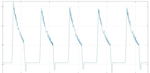
1. The battery used inside our device has a max discharge current of 5A (nominal operating current, limited by the safety board) and a peak discharge current of 10A (discharge cutoff current). We connect the battery to the battery charger thus to the system through BAT/SYS pins. SYS pin supplies digital power (through a 3V3 linear regulator) and directly provides power to a motor driver that drives a brushed DC motor. Such motor may draw up to 12A in stall condition (hence also in fast startup transients). However, BCD motor driver is limited to chop currents higher than 6A. Therefore, the intrinsic limit of the battery charger of providing 5A rms current and peak current (even if for a very short duration of 1us) of 9A should not constitute a problem for the functioning of our device. Morevover, the big bulk capacitor on the motor driver (470uF) helps the battery-battery charger system dealing with inrush currents peaks. The obtained results confirm such hypothesis, as the device operates correctly with accetable voltage ripples on VSYS during motor operations (note that we actually need to provide fast startups of the motor from 0V to max Voltage).
However, if we may need to increment the motor current, we thought about connecting the battery directly to the motor driver, and using the SYS pin only to supply digital power (or not using the SYS out pin at all).
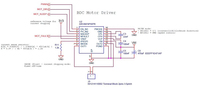
My question is: what are the most critical disadvantages in such direct connection, thus not exploiting the Narrow VDC Architecture of the battery charger? Is it feasible? Moreover, concerning the motor driver DRV8874, since we want to increase the maximum current above 6A, could you suggest a similar part number with higher current limitations? (since DRV8874 has a peak output current of 6A and above such value overcurrent protection may trigger)
2. Protection diodes on BAT and SYS.
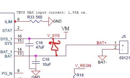
I saw on the schematics of BQ25886 Evaluation Module that you add a Schottky Diode between BAT and SYS nets. Is it only used to protect the internal BATFET from voltage spikes when connecting the battery?
Since we are driving a DC motor, it may occurs that during breaking some current is fed back into the battery charger. Does this reverse current constitute a problem for the battery charger? Can some internal protections be triggered thus disconnecting the battery from the system? (this is unwanted, since in normal functioning of the device we use only the battery to supply the system, no supply is connected to VBUS, and in any case VBUS+converter would not be able to provide sufficient power to the system, we would always operate in supplement mode). May be necessary to add a diode on VSYS net to avoid reverse polarity (current can only exit from SYS pin, not enter)? This would reinforce the hypothesis of 1. to connect the battery directly to the motor driver.
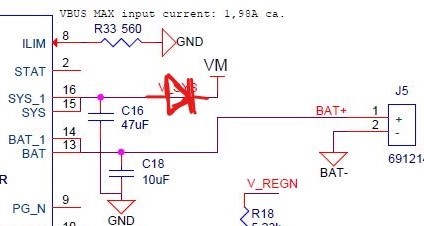
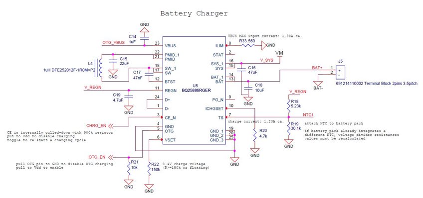
3. Maximum VBUS input current limit is clamped to ca.1.98A using 560Ohm resistor (we use a 5V-10W/2A wall-adapter to recharge the battery). Moreover, ICO algorithm is enabled by shorting D+ and D- lines. Maximum charge current is set to ca.1.23A using 4.7k resistor.
My question is: given the maximum VBUS input power (VBUS voltage, VBUS current) hence the maximum converter output power (charge voltage, charge current), is the charge current primarily limited by the maximum output power of the converter? To be more clear, is there the risk of overloading the adapter also when charging only (SYS draws very little current) due to a high set max charge current? (extreme case example: max VBUS input current set to 1A, max charge current set to 2A, adpater+converter is clearly not able to provide such current). Should be better to further lower the max charge current considering the max output power of the converter?
Thank you so much. Kind regards.