This thread has been locked.

If you have a related question, please click the "Ask a related question" button in the top right corner. The newly created question will be automatically linked to this question.

BQ25713: Cannot read chip ID when debugging the charging function

Part Number: BQ25713
Other Parts Discussed in Thread: BQ25700, , BQ25700A, BQSTUDIO, EV2400

Hi All,

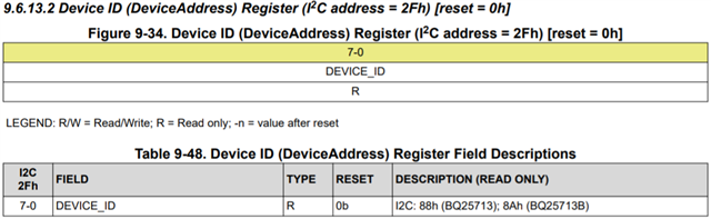
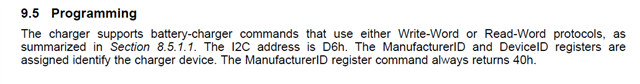
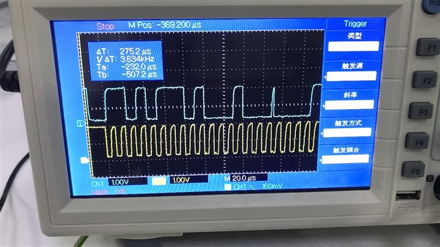
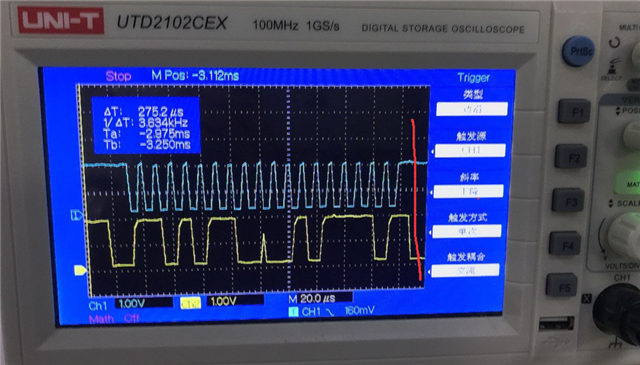
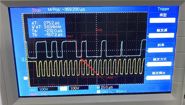
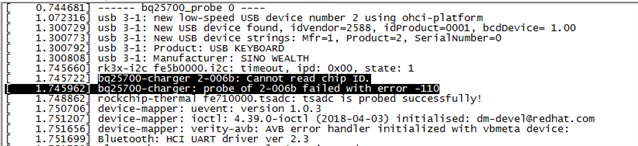
One of my notebook project, when debugging the charging function, it was found that the CHIP id could not be read. The return information is as follows: 

The dts configuration is as follows:

bq25700: bq25700@6b {
                compatible = "ti,bq25703";
                reg = <0x6b>;
                extcon = <&usb2phy0>;
                interrupt-parent = <&gpio0>;
                interrupts = <RK_PB7 IRQ_TYPE_LEVEL_LOW>;
                pinctrl-names = "default";
                pinctrl-0 = <&charger_ok_int>;
                ti,charge-current = <1500000>;
                ti,max-charge-voltage = <8704000>;
                ti,max-input-voltage = <20000000>;
                ti,max-input-current = <6000000>;
                ti,input-current-sdp = <500000>;
                ti,input-current-dcp = <2000000>;
                ti,input-current-cdp = <2000000>;
                ti,input-current-dc = <2000000>;
                ti,minimum-sys-voltage = <6700000>;
                ti,otg-voltage = <5000000>;
                ti,otg-current = <500000>;
                ti,input-current = <500000>;
                pd-charge-only = <0>;
                status = "okay";
        };

The circuit diagram design is as follows:

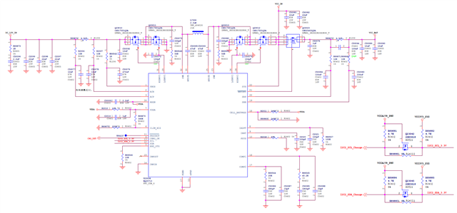
Can u pls help to analyze the cause of this problem?

Thanks,

Best Regards

  • Hi Lumina,


    By chip ID, are you referring to the DeviceID() register shown below?


    Please confirm which register address the host MCU is reading back when it tries to read the chip ID. The DeviceID() register address is 2Fh for the BQ25713. However, your logs mention the BQ25700. The BQ25700A is an SMBus device, and its DeviceID() register address is FFh, which is different.


    Are you able to read and write to the other registers normally?


    Best regards,

    Angelo

  • Hi Angelo,

    We changed the ID register address to 0x2F and still cannot read the chip ID, and other registers cannot read and write normally.

    By the way. Form the datasheet of BQ25713 we know that the address of I2C is 0xD6, and get no return when we read it.

    Can u help to analyze the cause of the problem?

    Thanks,

    Best Regards

  • Hi Lumina,


    Thanks for clarifying that you are unable to read or write to any of the registers, not just the DeviceID() register. Can you try using the I2C device address 0x6B instead of 0xD6?


    Best regards,

    Angelo

  • Hi Angelo,

    I have tried to using the I2C device address 0x6B instead of 0xD6 and got no return. Anyway, I have update the complete log information, and u can check it.log_kernel_0315.txt

    By the way, is there a problem with the hardware schematic design?  What can I do to help you(your team) to locate this problem and solve it?

    Thanks,

    Best Regards

  • Hi Lumina,


    I don’t think your schematic would cause these I2C communication issues. Please try the following steps so that we can debug this:


    1. Does I2C communication work if you use an EV2400 with BQStudio? This will quickly show us whether there is a software issue.
    2. Please capture a waveform showing SDA and SCL on the same graph during an attempted register read or write. We want to see whether the timing requirements in Table 8.6 in the datasheet are being met when you use your own host MCU to communicate with the BQ25713. You can also capture the SDA and SCL waveforms while using the EV2400 and BQStudio so that we can compare the timing with your own MCU.

    Best regards,

    Angelo

  • Hi Angelo,

    Sorry I don't have a EV2400 for the testing. But I have capture the waveform showing SDA and SCL as follows:

    Thanks,

    Best Regards

  • Hi Lumina,


    Thanks for sharing the waveforms. Please see my comments below. If at all possible, I strongly recommend ordering an EV2400. The debug process will definitely be faster if we can compare the EV2400+BQStudio communication with your own host MCU. This is the clearest way forward.


    Also, if you have a BQ25713 EVM on hand, then you can try using your own host MCU to communicate with the EVM. This is another way to test your own software. Right now, it's best if we can eliminate as many unnecessary variables as possible by testing your board with known good software (EV2400+BQStudio), or testing your software with known good hardware (the BQ25713 EVM).


    The rise and fall times in the waveform above are very slow (clearly slower than your other waveform for some reason). It looks like the rise and fall times are both about 2 us, but the maximum rise and fall time defined in the BQ25713 datasheet is only 300 ns. The very slow rise and fall times may explain why SDA only rises up halfway for one of the pulses, and then it already has to come back down. Please probe SDA and SCL as close as possible to the BQ25713's pins. In other words, probe I2C2_SCL_3.3V and I2C2_SDA_3.3V in your schematic, not I2C2_SCL_Charge and I2C2_SDA_Charge.


    Several comments about the waveform above:

    • The 1st byte is 0xD7, not 0x67.
    • The 8th bit of the 1st byte is the direction bit. If the 1st byte is 0xD6, this is a write operation, while 0xD7 is a read operation. However, the communication shown in your waveform is not the correct format for a register read. The correct format is shown below, and it looks like your waveform is missing the first 2 bytes. Is there more SDA/SCL activity right before your waveform that we can't see in the image?
    • For a register read, don't forget about the second START condition which must be sent after the first 2 bytes. Please see the following E2E thread for more information, as well as an example at the end which shows the correct waveform for a register read: https://e2e.ti.com/support/power-management/f/power-management-forum/899423/bq25713-i2c---debug-lack-of-answer


    For now, let's just focus on reading the manufacturer and device ID from register 0x2E (same as the E2E thread above, so you can try to make your I2C communication waveform match the example at the end). Also, it would be helpful if you have a logic analyzer so that we can see all of the I2C communication in a single image, with the bytes already decoded.


    Best regards,

    Angelo

  • Hi Angelo,

    Thanks a lot.

    We have solved this problem.

    Best Regards

  • Hi Lumina,


    Thank you very much for the update. I'm glad the issue is resolved. Could you please share what the problem was? This may help us debug similar cases in the future.


    Best regards,

    Angelo