This thread has been locked.

If you have a related question, please click the "Ask a related question" button in the top right corner. The newly created question will be automatically linked to this question.

BQ25792: BQ25792 stopped working when powered by an external 24 VDC source and without battery connected

Part Number: BQ25792

Hi,

We are working on a new board using a BQ25792 powered by an external 24 VDC source. Nevertheless, during the first test without battery connected, the device stopped working. To be noted that, after this test, the BQ25792 seems to work fine when we use a battery as power supply, but the DC power supply line seems to be shortcut in the BQ25792.

We made some tests with your evaluation board (BQ25792EVM) and we can't reproduce the problem.

We compared our schematic against yours (BQ25792EVM) without finding the source of the malfunction. We also try to modify our board to match your evaluation board as close as possible without fixing the issue.

Can you look to our implementation and tell us if you notice something explaining our problem?

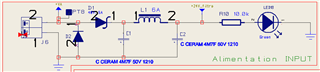
Attached with this message, you can find our schematic.

Best regards,

Anthony.

BQ25792_sch.pdf

  • Anthony,

    I see no obvious errors on the schematic.  

    With no battery, the charger requires charge to be disabled by CE bit or pin or TS fault due to missing thermistor.  If not disabled, the charger converter periodically stops switching due to OVP fault.

    How closely does your board layout match the EVM?  This device is very sensitive to capacitor placement and layout, especially the PMID and SYS capacitors.

    Regards,

    Jeff

  • Jeff,

    Thank you for your quick response.

    To add some details, when no battery is connected it means that thermistor is missing, so we have a TS fault, so the charge should be disabled, but have this malfunction anyway.

    We tested our board by powering it with 12 VDC and we didn't have any problems. We then gradually increased the voltage from 12 VDC to 24 VDC and it worked fine. But when we powered it outright with a 24 VDC source, the device (BQ25792) stopped working.

    Furthermore, we can observe a voltage spike at the inductor's terminals when we power it with 12 VDC, and we don't see this spike on your evaluation board. We don't know if the spike happens when powered with 24 VDC due to the BQ25792 breakdown.

    Attached to this message, you will find our layout for the BQ part.

    Regards,

    Anthony.

    BQ25792_Layout.pdf

  • Antony,

    Regarding your layout, unfortunately, the ground return for the SYS and PMID capacitors is too resistive and inductive, creating switching noise. Switching noise injected into the chip limits its maximum output current significantly.  Therefore, the charger requires the SYS and PMID capacitors GND return to connect to the GND on the the same layer as the IC.  Also, in this new package without a powerpad, each pin helps heat sink the IC. That means that the SWx traces need to go under the IC and then via down through another layer then via back up to the inductor.  If you also add a GND trace under the IC and then multiple vias to another layer with GND, the charger has adequate heatsinking. Check out BQ25792EVM user's guide or datasheet page 128 for the recommended layout.

    That said, I would not expect IC damage from your layout but the charger will not be able to reach maximum output current as specified.    Does your input supply overshoot at startup? What is the setting of the AC OVP register bits 4-5 in REG0x10?  Is the EN_HIZ bit in REG0x0F bit 2 set after this startup?

    Regards,

    Jeff

  • Jeff,

    Thank you for your advice on our layout.

    Our power supply doesn't overshoot at startup. You can see bellow the value of some registers :

    REG48_PART_INFORMATION_REGISTER : 0x08

    REG0F_CHARGER_CONTROL_0 : 0xA2

    REG10_CHARGER_CONTROL_1 : 0x85

    REG1B_CHARGER_STATUS_0 : 0x2F

    REG1C_CHARGER_STATUS_1 : 0x6A

    REG1D_CHARGER_STATUS_2 : 0x01

    REG1E_CHARGER_STATUS_3 : 0x00

    REG1F_CHARGER_STATUS_4 : 0x00

    REG20_FAULT_STATUS_0 : 0x00

    REG21_FAULT_STATUS_1 : 0x00

    Regards,

    Anthony.

  • Hi Anthony,

    Does your charger start working again if you remove and then replace the power supply with a lower voltage?  If so, can you recreate the problem and read one time all of the fault registers immediately after the charger stops?  The fault registers clear after being read.

    Regards,

    Jeff

  • Hi Jeff,

    The charger isn't working again regardless of the supply voltage. We can't read the registers because of the breakdown happens instantly.

    We can observe some short-circuits between GND and PMID, SW1, and REGN. We speculate that the problem comes from the internal LDO or DC/DC, but we can't find the source of it.

    We are making some others tests on our board, to see if there is a high current draw due to our system.

    To be noted that we use this chip on an other board and with the same schematic for the BQ, but using a different system, the board works fine.

    Regards,

    Anthony.

  • Anthony,

    If there are shorts between REGN and/or PMID and/or SW1 to GND, the IC is damaged.  This type of damage is similar to what happens when VBUS is overvoltaged >30V.

    Regards,

    Jeff

  • Hi Jeff,

    Our board is powered by a laboratory supply through a filter circuit composed by a TVS diode, a Schottky diode, and a pi filter.

    So, we looked with the oscilloscope the voltage that the BQ25792 gets at this pin VBUS, and all is clear, we can't observe any overvoltage.

    We tried to disconnect all the system after the BQ25792, to see if we still had the problem, and it was still there.

    We also tried to increase the contact surface between the GND pads and the ground plan of all the capacitors to improve the power discharge, but the result was not conclusive.

    Currently, the only difference between our two boards (a functionnal one and a not so much one) is the layout.

    Regards,

    Anthony.

  • Anthony,

    I have not supported many customers who have added a pi filter in front of buck converter so I can't provide advice there.  My suggestion would be to monitor the voltage at VAC and VBUS at start up, during line and load transients and power down, looking for spikes.

    Regards,

    Jeff

  • Hi Jeff,

    I have a good news, after extended testing we found the cause of our problem. Our GND route was located under a self that induced voltage fluctuations on the GND line leading to the malfunction of the BQ25792, so it was effectively a routing problem.

    It may help others to include a note in the doc about this issue.

    Thank you for your support.

    Regards,

    Anthony.