This thread has been locked.

If you have a related question, please click the "Ask a related question" button in the top right corner. The newly created question will be automatically linked to this question.

UCC27714EVM-551: Massive peak current (primary side) under no load condition

Part Number: UCC27714EVM-551
Other Parts Discussed in Thread: UCC28950,

Hello,

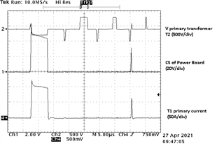
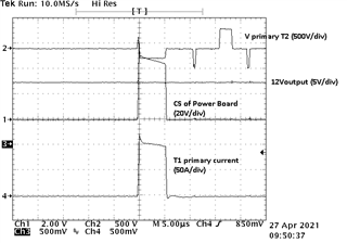
I've been testing the UCC27714EVM-551 board, and under no-load condition I saw on the CS pin of the Power Board (not exactly the CS pin of the UCC28950, as there's a 1k-330pF RC filter between both) peak voltages of around 40-60V.

Seeing the current through the primary of T1 (current-sense transformer), it was confirmed, as there were peak currents of about 100A with a duration of less than 10us.

Apparently, there was little to no effect in the 12V output.

With a minimum load of about 2W this effect this disappears.

1) Why is this happening? 

2) How is this not dangerous for the UCC28950 (CS pin) or for the primary mosfets?

3) Could it be related with the problem the user reported in this thread? UCC27714EVM-551: About cause of destruction of evaluation board - Power management forum - Power management - TI E2E support forums 

Thank you.

  • Hello Jose,

    The problem you are seeing seems to be related to the controller  current limit response and cycle to cycle operation. This could be potential noise problems, can you confirm the connections of the bias supplies and see if the bias voltages have excessive peak to peak noise?

    Since this may be a controller related question, and I am the driver support apps, you may want to post in a thread referencing the UCC28950 to get more detailed advice on this controller.

    Regards,

  • It seems to be related to my set-up for the measurement. 

    In these conditions (no-load), the connection of the ground of the oscilloscope to the control GND is definitely related to this effect.

  • Hello Jose,

    That is good news that you seem to have identified probe setup affecting the issue you are seeing.

    For benefit of others on the forum, can you describe the probe setup that creates the issue and what may resolve the issue?

    Regards, 

  • Hello,

    As I said, with the GND of the oscilloscope connected to the control GND (while monitoring the CS signal), these current peaks appeared with no-load at the output.

    Adding also two differential probes between G and S of Q1 and Q3 or Q2 and Q4, these peaks were still high but not so much as only with the probe connected to CS and control GND.

    Disconnecting the ground wire of the probe from control GND, I didn't see the current peaks.

    It appears to be related to noise in the drivers or something like that in these particular conditions, because with a minimum load of 100mA at the output, this problem disappeared. With currents of around 100A with no effect at the output, and seeing that the primary transformer voltage is about half the Vbus during these peaks (see my first post), it could be a shoot-through, some mosfet in the linear region, or something like that.

    I have read in other posts that 0.022uF capacitors are recommended between G-S of the primary mosfets. My board doesn't have these capacitors. I don't know if they could have also an effect for this problem.

    Regards.

  • Hello Jose,

    Thank you for the details. The 0.022uF capacitors are beneficial to help reduce Vgs perturbations on the Mosfets. I would recommend adding these. close to the MOSFET devices across the gate to source resistors.

    Regards,