


Other Parts Discussed in Thread: PTD08A020W, UCD9248, UCD7242
We have an FPGA board design, whose power rail circuitry is heavily based on the Xilinx VC709 architecture, as such we have UCD9248 power controllers and PTD08D210W & PTD08A020W power modules.
We've built of order 60 or so boards, previous batches we've never observed any issues, but on the last batch of ~30 boards, we are seeing very intermittent power sequencing issues on startup with about 6 of the boards.
I've spent some time diagnosing the problems on 3 of the boards, and I am seeing the same thing, on each of them, one of the rails on a PTD08D210W (always the same rail and the same part) is registering an FLT Fault which is then killing the power sequence and causing all the rails to shut down.
This intermittent FLT issue is only occurring when the boards are powered from one specific bench supply (the only thing I can put this down to is it has a much faster ramp up time than our other PSU's) and also more puzzlingly will only occur when the TI programmer (for PMBUS programming or monitoring of the UCD9248's) is detached, if the cable is attached we never see the issue.
Having put a scope on various points, see below:
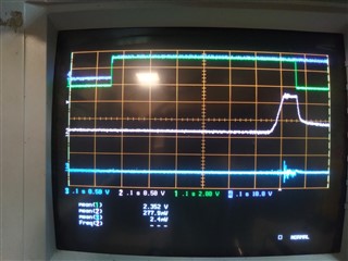
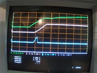
The traces are as follows:
- (Green) The FLT pin from the problem rail / part.
- (Pink) 1.2V rail, from earlier in the power sequence
- (Blue) The rail from the problem rail / part (should be 1.5V)
- (Purple) The input 12V supply to the board.
So in a normal operation, you'd never see trace 1 (the FLT pin) go high and the 1.5V rail would start up correctly and the sequence would complete. But as captured in this trace, immediately on power up the module has set the FLT flag on just that one rail, well before we even start trying to use it. There is then about a 0.5 s pause in the sequence, then the rails start being sequenced on, the 1.2V rail precedes this one, and the point where FLT clears and the rails turn off is where the 1.5V rail should be turning on. It appears that correctly the FLT fault is being cleared by a PWM cycle on that rail and no fault condition being present, but apparently the clearing is to late for the controller which detects an FLT state, flags an error and disables all the rails.
Annoyingly in Advanced options -> driver config, it is set to ignore FLT state on start & restart, but obviously this doesn't seem to be having an affect.
Any ideas why it is being set from power on, why it is always the same rail (only one of them, its a dual rail part) on the same part on all our boards, I say all, I've checked on 3 and its the same one, I have no reason to believe it won't be the same on our other faulting boards.
And any idea how I stop it doing this, at the minute my only solution is to change the FLT input pins in the UCD9248 to just be GPI's and then completely ignore them, as the UCD's are monitoring the temperature and current during normal operation I am happy with this, but it doesn't seem right.
Regards,
Bryn


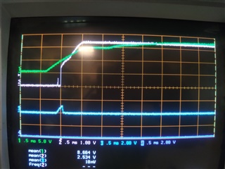
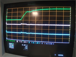 Power on with TI programmer attached.
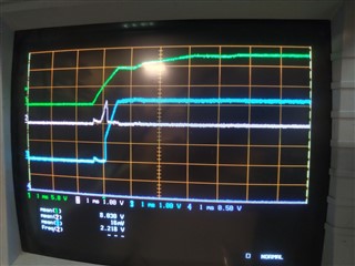 Power on with Ti programmer detached, and FLT being set.
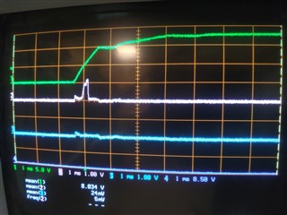
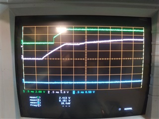
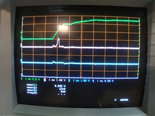 Power on with Ti programmer detached, and FLT not being set.
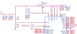
 Programmer detached, no FLT flagged.
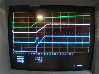 Programmer detached, FLT flagged.
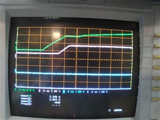 Programmer attached, no FLT flagged,