This thread has been locked.

If you have a related question, please click the "Ask a related question" button in the top right corner. The newly created question will be automatically linked to this question.

UCD9248: T on delay overrides T rise & FLT not being ignored on start up

Part Number: UCD9248
Other Parts Discussed in Thread: PTD08D210W, PTD08A020W, , UCD7242

I have a system with 2 x UCD9248's controlling a number of power modules, PTD08A020W's & PTD08D210W's.

The first rail to be sequenced I set to have an on delay of 500 ms then to have a rise time of 50 ms, this is driving the PTD08A020W's.

When checking on a scope I see the correct on delay but the rise time is almost immediate, if however I turn the on delay to 0 ms, I see no delay and a correct rise time.  I tried leaving the on delay at 500 ms and setting the rise time to 550 ms, and what I see is nothing for 500 ms then a big jump up to nearly full scale, then 50 ms of a very slow ramp, as if its been ramping from 0 ms with the aim of completing at 550 ms.

It looks like the ramp is applied from T 0 at whatever you set the rise time, and then the output is just gated with on delay, so if its already ramped up its just straight on.  I don't think that is what is intended by the settings is that expected behaviour?

The second issue I'm having is related to this issue (+) PTD08D210W: FLT flag being set from power on - Power management forum - Power management - TI E2E support forums whereby I am seeing one module have its FLT flag set from power up, this is causing my sequencer to immediately abort sequencing and shut down.  Looking in Advanced options -> driver config, it is set to ignore FLT state on start & restart, which I would expect t stop this problem, but it doesn't, any idea why the setting appears to have no effect?

Thanks,

Bryn

  • 1- Please post your schematic/configuration file/waveforms of the soft start behavior. I am wondering if maybe you inadvertently have voltage tracking enabled. 

    2- Have you looked at the status flags from UCD9248 when the power-on fails? This may contain some clues, since you have the file configured to ignore the FLT. 

  • Hi,

    1) Schematic page for the relevant UCD9248 attached below:

    Configuration file for that part:

    UCD9248 @ Address 52d Project.xml

    Its the very first rail to start, so I'm fairly certain I have no voltage tracking turned on.  If you need waveforms, that may take a bit longer as I'll have to create a setup in the lab to capture it, let me know if you think they are required, may not be till next week though.

    2) When you say the status flags do you mean whats reported in the software, if so, the rail reports an FLT fault and that its output is off.  Which confuses me as that setting implies it should ignore that type of fault.

  • Hello,

    1- Can you try to decrease the DRIVER MIN PULSE command? Here is a snapshot from the UCD92xx user guide. I get a Vstart of appx 0.84V on this rail (12v * 140ns * 500kHz). 

    2- By status flags, I mean the Status registers on UCD9248. Does it make a difference if you set the FLT1/2/3/4 pins on UCD9248 to "Unused" ?

  • 1) I will capture some plots of what it is doing next week, and try the DRIVER MIN PULSE command at the same time.

    2) Yes the status registers say FLT fault.  I would like to set the FLT pins to be unused but it won't let me, however I can set them to GPI and then just not use them which has the same effect (this is what I am currently doing).  Problem being I can only define 4 GPI's per device and I am already using some so I still have some FLT's connected which may well come back to bite me, can I force the pins to be unused? 

  • I did see that Rail 1 still has the FLT pins being used. I agree setting to GPI with no sequencing dependencies should be ok too. 

  • Is there a way of setting the inputs to unused, so I don't hit the limit of only 4 GPI's as ideally I'd like to ignore all the FLT inputs if they are potentially going to be problematic.

  • The FLT functionality can only be disabled by setting the pin as a GPIO instead. First I think we still want to figure out what is causing the FLT to trigger. Short of that, one idea I can think of (without changing the board), would be to set them as GPO->OC Warning pins, and set the OC Warning on these rails such that it will never trigger (like 999A). 

  • As mentioned in my first post I have another thread in the forum on the FLT flag issue, I was just trying to resolve in this thread why the ignore FLT on startup setting wasn't working.

    So below are 4 plots I captured of startup ramps:

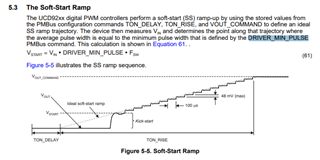
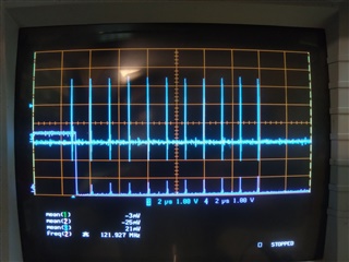
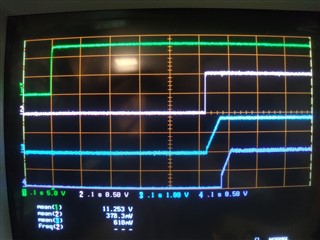
    1)   Ton = 500 ms, Driver Min Pulse = 140 ns.

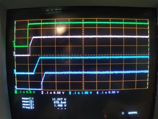
    2)   Ton = 0 ms, Driver Min Pulse = 140 ns.

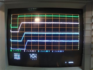
    3)   Ton = 0 ms, Driver Min Pulse = 70 ns.

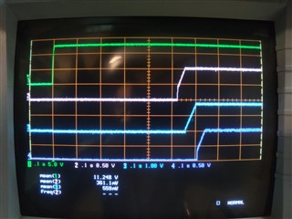
    4)   Ton = 500 ms, Driver Min Pulse = 70 ns.

    So you were right lowering the Driver Min Pulse does get you more of a ramp. less of a start off voltage.  But increasing the Ton delay is also causing that start off voltage to change upwards.

    Increasing the Ton to 500ms, makes the start off voltage raise by ~0.25V for 70 ns Driver Min Pulse, and ~0.5V for 140ns Driver Min Pulse.

  • I see. I am not really sure what causes the kickstart level to be dependent on the TON DELAY, but I guess you can just reduce the DRIVER MIN PULSE to the point the rise time is monotonic with your desired sequencing configuration. 

  • What impact does DRIVER MIN PULSE have on the system as I note it is a design controlled value, when I over rode it in advanced settings it warned me my design task was now out of sync and it was disabling the auto functions from that, will making the time less impact some other feature of that rail?

    Any progress on the ignore FLT setting not working, as I'm concerned I'm not ignoring all the rails, and the other thread looking at this seems to be running out of steam with them suggesting I use the ignore work around?

    Bryn

  • The DRIVER MIN PULSE is related to the minimum pulse width the controller will pass to the power stage. So, in addition to the startup condition, I would also suggest to look at the soft-off condition if you use it. And, it may also limit the conversion ratio, if your system will adjust the voltage lower on-the-fly. 

    Have you tried looking at the ISENSE and Tmon pins of the PTD08A020W's? Ostensibly, these should be the values which cause FLT to assert. 

  • Hello, There is an interesting observation in the other thread about not having this issue when the PMBus connector is plugged in. Can you plot the power-up of 3.3V vs. 1.8V, vs. PWM/FLT here? I am wondering if the 1.8V comes up first, and gives a leakage path through the NMOS level translator back to the controller to allow this to occur. 

  • Hi,

    I'll go and capture some waveforms now, but what 1.8V are you talking about?

    Bryn

  • I'm referring to this from the other thread. There can to bias the PMBus lines before the controller gets biased through it. 

  • I've attached some plots to the other thread.  It looks to me like the programming cable is partially powering the UCD's when plugged in so avoiding the blips on start up.

    Tmon on the module is monitored by the UCD and I don't see any massive temperature spikes, we don't look at ISENSE as we monitor the current via separate sense resistors in the UCD.  Do you want me to look at the ISENSE pin, we don't route it out but I should be able to get a probe on, will it tell you anything?

    Have you managed to discover why the ignore FLT setting doesn't do what it says on the tin, or am I reading it wrong?

    Bryn

  • Sorry Matt,

    I was composing my last reply as you replied so I missed it, in answer to your question, the 1.8V is controlled by the same sequencers, so won't be on at start up, it is sequenced before the 1.5V rail (the one we are seeing the FLTs on), but probably 600 ms or so after the FLT flag being set.

    Bryn

  • I see. Thanks. 

    It actually looks to me like the FLT is not going down until the rail gets disabled, so it would still cause a shutdown at the end of soft start. 

  • I haven't actually captured a zoomed in view of that time, but the description of the FLT flag in the module says it is cleared by the receipt of a PWM cycle when there isn't a fault.  It gets cleared and the rails shut down at the instance when the rail should be starting to turn on, so I assumed it was because it had received a PWM cycle and there wasn't a fault.  I haven't captured this, but I could do.  There is no way the module knows the rail is disabled other than a lack of PWM cycles so I don't think it is clearing because the rail is disabled. 

  • I see your point here about enable. It would still be good to see this region, and look at the PWM to see if the rail did indeed start pulsing PWM before stopping and shutting down with a fault. To me, actually it would mean its possible maybe the "ignore FLT during power-up" option was effective, and the UCD9248 stopped switching for some other reason. 

    One thing I would like to ask about from the previous thread. You found that with the USB adapter being plugged, the bias to the UCD9248 is pre-biased. And I also notice the glitch on PWM is appx at the same slew rate as your Vin coming up. Have you tried to reduce the slew rate of these input supplies to see if there is an impact? Also, I am wondering if there is an impact to add a pull-down the FLT or even a small cap on PWM (or even a divider to bias PWM in the tri-state region at power-on). Earlier I was concerned about the ISENSE pins floating, but after checking with Yitzhak, the Isense pins do have a pull-down inside the module. 

  • Right, I made some captures yesterday of the region when the FLT is cleared.  Trace 1 (green) is Vin (12v) just plotted as it was attached.  Trace 2 (pink) is PWM,  trace 3 (blue) is the FLT flag.

    These captures are done on my board with the fixes to ignore the FLT input so the rail doesn't shut down it just carries on ignoring the fact FLT is flagged, but you can see FLT is cleared on either the first, second or third PWM pulse.

    Normally it was the first PWM cycle that cleared it, but I did occasionally see second or third, hence the captures.

    If you need me to re-enable the FLT checking and recapture let me know, but you can clearly see its the PWM's that are clearing the fault, and in my initial measurements the FLT was cleared at the same time as the rails shut down, so I am fairly certain the setting is doing nothing.

    In answer to your other question, we never saw this issue on our other bench supply which has a much slower slew rate, so I would say you are correct the slew rate of the incoming supply does have an impact, I haven't captured a plot to prove this one way or the other.  However, that input is the main input to our boards, as such is out of out control when installed in a system, so slowing it down is not an option.

    How would a pull down on FLT help when its being actively driven by the module?

    Would a cap on PWM not affect the waveforms under normal operation?

    Regards,

    Bryn

  • Hi Bryn, 

    Just want to check, did the rail power-up normally after this? And it would stop after one pulse on PWM if the other changes were not done?

    If lowering the 3.3V slew rate really helps, we should be able to do that by increasing the value of C198 in your schematic, since 3.3V is generated by the pass NPN device. I'd be interest to see if you increased it to 470n-1uF as an experiment if the FLT stops coming up. 

    I'm thinking the reason you see the blip on PWM is related to power-on not being well controlled. So, if the PWM were biased, it might have helped prevent it from setting and staying set. 

  • Hi Matt,

    Yes the rail powered up correctly on all those plots as I was ignoring the FLT input.  Do you want me to do a capture with the software set back to taking note of FLT to see how many PWM cycles are observed?

    I don't know if lowering the 3.3V slew rate helps, I can only comment on the 12V slew rate, which I guess if slow enough probably does limit the 3.3V slew rate.  Again I can do a capture on our slower power supply so we can see the 3.3V slew rate and PWM if you think that may shed some light.

    If that looks promising I can get someone to swap out the cap for a 1uF one if you think that may help.

    Although looking back through my plots on the other thread I'm not sure that will help as it looks like PWM is going high before the 3.3V for the UCD does, as if its being fed back through the PTD module, what do you think?

    Bryn

  • It would help to see if the controller still fires PWM pulses, and how many (though i suspect it is not many). It's possible there's some kind of race condition where the controller ignores the first one, but if the power stage did not clear it, then the FLT fault re-triggers in the controller. 

    It would help to see if the PWM blip is related to the VIN rising rate, or the 3.3V. I'm thinking it should be due to 3.3V, since that's where the pull-up on the PWM pins goes to. It would be good to know (1) if the slower slew rate on Vin eliminated the issue, and (2) if keeping the same 12V supply, bot slowing down 3.3V solves the problem. I ask this because of your earlier osbservation that pre-biasing the 3.3V due to the PMBus dongle seemed to help alot. 

  • HI Matt,

    I've rolled my controller chip software back so I now pay heed to the FLT flag and captured the following plot:

    The blue line (3) is the PWM from the controller to the module, the purple line (4) is the FLT flag reported by the module.

    You can see the FLT flag is set (and has been since power on), the first PWM cycle clears the FLT flag, the controller generates a few more PWM cycles then shuts the rail down.  When I check in the software, rail 4 which is the one I am monitoring reports an FLT fault.

    So seemingly it is heeding the state of the FLT pin on startup, even though Driver config is set to ignore.

    I'll try and setup now to monitor Vin, 3v3, and the PWM, see if I can investigate if ramp rates has an affect.

    Bryn  

  • Hi Matt,

    I've done some captures detailed below:

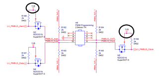
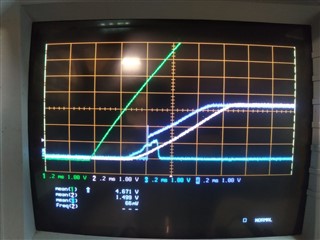
    1)   - Fast ramp 12V PSU - 0.2 ms per div

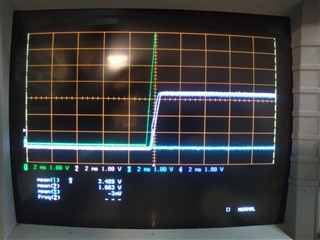
    2)    - Fast ramp 12V PSU - 2 ms per div

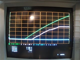
    3)   - Slow ramp 12V PSU - 2 ms per div

    On all plots the scale is 1V per div so its easy to match voltages and I've aligned the 0v positions so they are easy to compare.

    Trace 1 (green) is Vin (12V) to the power module and the transistor generating 3.3V for the controller.  Trace 2 (pink) is the 3.3V generated by the transistor of the controller controlling rail 4.  Trace 3 (blue) is the PWM signal for rail 4.  Trace 4 (purple) is the FLT flag for rail 4.

    Looking at plot 1, I don't think slowing 3.3V will have any affect on the PWM blip as it can be clearly seen it is exceeding the voltage on the 3.3V rail, so I would say it is being pulled up by Vin, not 3.3V.  Slowing the 3.3V down will probably just make it bigger.

    Plot 3 however shows that the 12V can be high a long time before 3.3V and it doesn't cause a blip, so I wonder if its the voltage difference.  On the slow ramp, Vin is never more than ~1.5V above the 3.3V until the controller is on, however on plot 1 & 2, the Vin is ~ 4V above 3.3V when it starts turning on and the difference is rapidly increasing.

    Could there be some sort of pull up / clamp diode effect we are seeing, that is only present when Vin is so much higher than 3.3V?

    Cheers,

    Bryn 

  • I see, it looks like there may well be an ESD diode or leakage path from Vin to PWM... This may not be a solution, but I assume everything would power on normally with another toggle of the enable, or operation command.?

  • Correct, if I get it sat in its 'off' state indicating its seen a 'FLT' fault, I can issue a 'turn on' operation command from the GUI and it all comes to life, rails on correctly. 

  • Hi Bryn, Sorry for the late reply. I am wondering if adding a capacitor in parallel with R68 can be an acceptable work-around. This would make the 12V as sensed by the controller move slower than in reality and hopefully prevent such glitching on the PWM pins. 

  • Hi Matt,

    I think that will make it worse.  Looking at the plots it is the 12v into the power module that's causing the issue, it seems to be that is somehow leaking through the module onto the PWM input, pulling it up, and its only when the controller wakes up that it pulls it back low correctly.  Slowing the 12v into the controller will either have no effect, or make it slower doing that.  I would say we need to slow the 12v into the power module, but I can't see how that is achievable.

  • Hi Brynn, Is the PWM coming up through a leakage path in the controller, or from the module? I'm not sure if we have established that. 

  • Hi Matt,

    I would say it is the module, the controller is powered from 3.3V, and can only see the incoming 12V on that sense input, which is run through a potential divider, meaning the controller only sees 1/6th of the input rail.  Looking at plot 1 above the PWM blip breaches 1V well before the Vin passes 6V, which would be where the controller would see 1V, the peak of the blip is ~1.2V, at that point Vin is ~5.5V, which I think means the controller won't be seeing anywhere near 1.2V, so to my mind it has to be the module.  What do you think?

  • Ok. I see your point. In that case, I'd be willing to bet this is correlated to the power-on of the UCD7242 BP3 LDO, or VGG LDO, both of which are self-contained in the module. Example, the PWM is rising while 12V is high, and BP3 is soft-starting. I may have suggested this before, but does it help to add a loading resistor on the PWM pins, which the controller can overdrive during operation (you might actually want a divider so when the controller tri-states, the pin floats to mid-level). 

  • I've not tried loading resistors on the PWM pins.  Without the details of exactly what the controller can drive out in terms of current, and what the module itself expects in terms of VINH & VINL thresholds, I'd be loath to just try sticking random resistors on the board.  Is that sort of details in the data sheets, I don't remember it being mentioned, but then we just wired up as per the example circuits and assumed that bit would work.  My worry is just sticking a resistor on would affect our PWM waveforms and then I'd be affecting the rail outputs during normal operation.

    Is there no way the ignore FLT fault on startup setting can be investigated, as surely if that worked that would remove the need to do any of this tinkering.  It seems to me that's exactly what that setting is for, but it doesn't seem to work.

    Bryn

  • Hello,

    On the controller, the PWMs are considered digital outputs and their Max VOL/Min VOH is given in the electrical table. 

    This module uses the UCD7242 power stage IC which also has the PWM input thresholds specified .