This thread has been locked.
If you have a related question, please click the "Ask a related question" button in the top right corner. The newly created question will be automatically linked to this question.
Hello we have an issue with our design.
The design is a power supply from 30-48V to 12V 10A.
We used we bench to design the power supplyr. The load can be plugged and unplugged. We have tested the design with a resistive load and an inductive load(motor). The design do the job but some times the high side mosfet Q8 burns (0 ohm between Source an Drain).
The gate signals of both mosfet at full load are :
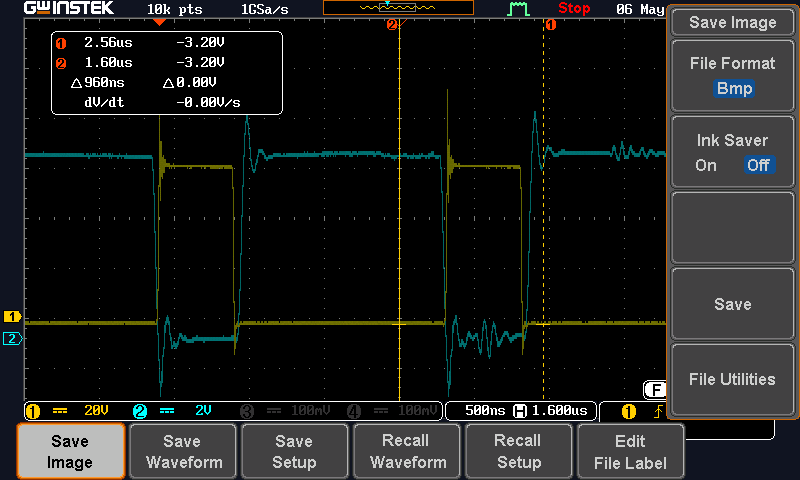
The gate signals seem to be ok.
But when there is no load we have:
Zooming on the off section we see that there is a cross conduction with High side and low side mosfet color signal are( inverted here) the ringing section here on low side gate mosfet have been removed after.
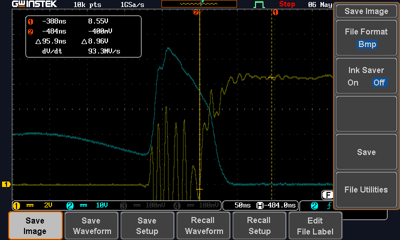
The sw signal at no load is
We do not know exactly when the high side mosfet burns but we suspect that occurs when we switch off the power supply or when we unpplug the load.
Sincerely
Johan
.
Hi Johan,
This seems quite similar to the LM5145 EVM in terms of MOSFET selection. Actually, it's similar to the LM5146-Q1 EVM as well as that's 12V/8A/400kHz.
Please send a completed LM5145 quickstart file. I see the output is a bit low here, so please use the correct derated value for ceramic output capacitance.
In terms of the waveforms you provided, this corresponds to diode emulation mode (when the DEMB pin is tied low). As mentioned in the layout section of the datasheet, it's important to keep the gate loops as tight as possible to minimize parasitic inductance that may cause ringing. If you suspect that there is coupling from the SW voltage to the low-side gate (LO) during high-side turn-on, then a resistor (such as 4.7 or 10 Ohm) in series with the boot cap will slow the turn-on and hence the rising dv/dt of SW.
Maybe you can measure the SW voltage to see how that is behaving during switching. in particular, you can refer to app note snva803 for power stage layout guidance -- the LM5145 and LM5146-Q1 EVMs are actually based on the techniques discussed in that app note.
Regards,
Tim
Hello Tim,
We do the calculation with webench. We found the problem. We are using a motor connected on the 12V output The motor consumtion is 10A at 12V.
We made the monitoring of the 48V input. Some times the current reach 12Amps on the 48V input when we start the motor during a short time. This means that there is more or less 48A on the 12V branch. We suppose that there is more.
That's mean that the I limitat.ion does not work for short circuit. The BSC117 support 48A we see that we are at the limit.
We made a test changing the high side mosfet with a BSC037 that support 100A. The mosfet is ok know but as the RDSon of the BSC037 is 3 times higher the limitation occurs when the mosfet is hot.
What can make the short circuit limitation not working properly ?
Sincerely
Johan
Johan,
Please check the inductor saturation current if high currents are expected. Also, you can refer to the LM5145 EVM for current limit setting as it uses the same low-side FET. Note that the LM5145 has valley current limiting, so the peak current can run higher when the overload is initially applied (see the current limit section of the LM5145 datasheet for more detail).
Regards,
Tim