This thread has been locked.

If you have a related question, please click the "Ask a related question" button in the top right corner. The newly created question will be automatically linked to this question.

UCC5350: Miller clamp version and bipolar power supply & Clamp pin connection with parallel MOSFET

Part Number: UCC5350

Hello,

 I got questions about the UCC5350M with Active Miller Clamping.


1)      Is it possible to use bipolar power supply as -5/18V with the UCC5350M ?

 I expect to use SiC MOSFET and recommended gate voltage is -5/18V. With simulation model I can observe Miller effect and false turn-on with negative drive voltage ! Thus to overcome this problem, active Miller clamping seems to be a good solution. Using a Unipolar power supply with UCC5350M cannot be done on my application due to low threshold voltage of SiC MOSFET, clamping threshold voltage is quite above Vgsth, moreover gate charge is very low.

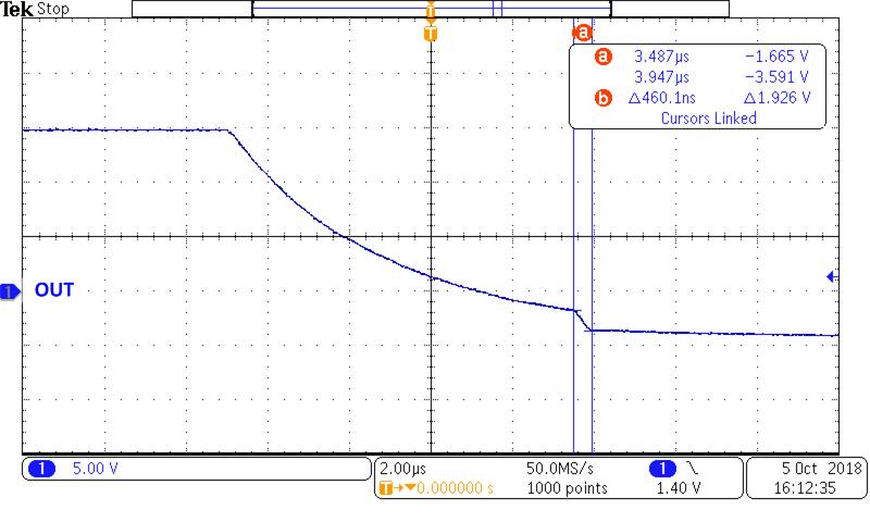
I tried to simulate UCC5350M on LTSPICE, it works fine with unipolar power supply. However it doesn’t with bipolar power supply. I expected to see activation of Miller clamp when the gate voltage rises above -3V (with -5V on negative drive). Simulation model seems not planned to be used with bipolar power supply.


2)      Lastly, Have you some recommendations about CLAMP pin connection to drive parallel MOSFET ?

My application requires to parallelize MOSFET. To limit oscillations and dynamic unbalance, I think to partially decouple gate as in Figure 5c of the following technical documents. (www.st.com/.../en.Design_rules_for_paralleling_of_Silicon_Carbide_Power_MOSFETs.pdf)

But decoupling resistor will increased the impedance of clamping path.


Regards,

Joris

  • Hello Joris,

    Welcome to e2e! I am the applications engineer for our single-channel isolated gate drivers.

    1) Can you post a picture of your schematic? I'd like to to see how you are implementing the negative turn-off. We usually recommend the Miller clamp with unipolar supplies and rely on negative turn-off for bi-polar supplies.

    I will look into the simulation files and see if there are any issues with the UCC5350M and bi-polar supplies.

    2) Figure 5c would be a good way to minimize parasitic oscillations as long as the same FETs are used, the trace lengths are equivalent and the gate resistance is the same.

    The CLAMP pin should be connected directly to the gate of the SiC FET.
    Any rise in gate voltage will be dampened by the gate resistors and the CLAMP pin might not respond fast enough if there are resistors between the CLAMP pin and the gate.

    Regards,
    Mateo
  • Hello Mateo,

    1) You will find attached two pictures with two different schematic. One referenced to the ground and the other to a floating point.

    On both case, the positive voltage is 18V as expected, but on negative voltage it doesn't reach -5V as soon as the driver is ON (IN- pulled to the ground). Negative voltage is clamped to approximately -3V.

    I tried to applied PWM on IN- at a lower frequency the switching frequency. Before first turn-on, negative voltage is 5V but after it is clamped to ~-3V.

    2) Ok, thus to ensure fast response and low impedance path it is recommended to not decouple SIC FET. 

    Regards,

    Joris

    UCC5350M_For_TIsupport.pdf

  • Hi Joris,

    I apologize, we missed your response. I'll ask Mateo to look into your issue on Monday.
  • Hello Joris, 

    Sorry about the wait! It took me some time to dig into the model files to figure out what was wrong. 

    Can you go into the netlist and make the following update:

    E_E36         GATE_CLAMPMOS VEE2 N17113570 0 1

    E_E36         GATE_CLAMPMOS VEE2 N17113570 VEE2 1

    this will make the clamping feature referenced to VEE2 rather than gnd. I will ask our modeling team to update the SPICE files that are posted on the product folder. 

    I hope this answered your question, if it did, please press the green button! 

    regards,
    Mateo

  • Hello Mateo,

    I modified the model as described but this modification brings others issues.

    You will find attached the schematic and simulation results.

    Regards, 

    Joris

    UCC5350M_For_TIsupport_libv2.pdf

  • Hello Joris,

    I will work with our modeling team to get this resolved and get back to you before the end of this week.

    Regards,
    Mateo
  • Hello Joris,

    Our modeling team is still working on this fix.

    I went ahead and used the UCC5350M with the UCC5320SCDEVM-058 and produced the following waveform to show proof of concept.

    Test conditions:

    VCC2 = 15V

    VEE2 = -5V

    Referenced to GND2 on EVM

    You can see the clamp activating ~2V above VEE2 which is about -3V.

    I'm going to close the thread for now and reopen when the modeling team has completed the spice model fix.

    Regards,
    Mateo

  • Hello Joris,

    The models have been updated on the UCC5350 product folder.

    Let me know if you need anything else from me. If not, please press the green resolved button.

    regards,
    Mateo