This thread has been locked.
If you have a related question, please click the "Ask a related question" button in the top right corner. The newly created question will be automatically linked to this question.
Hi,
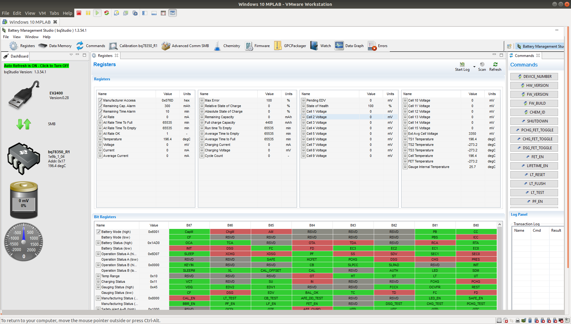
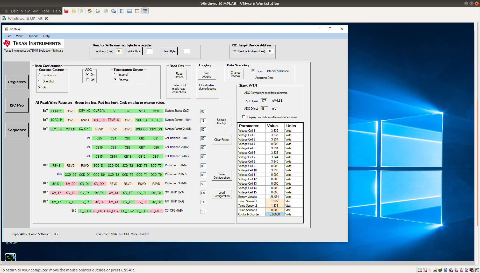
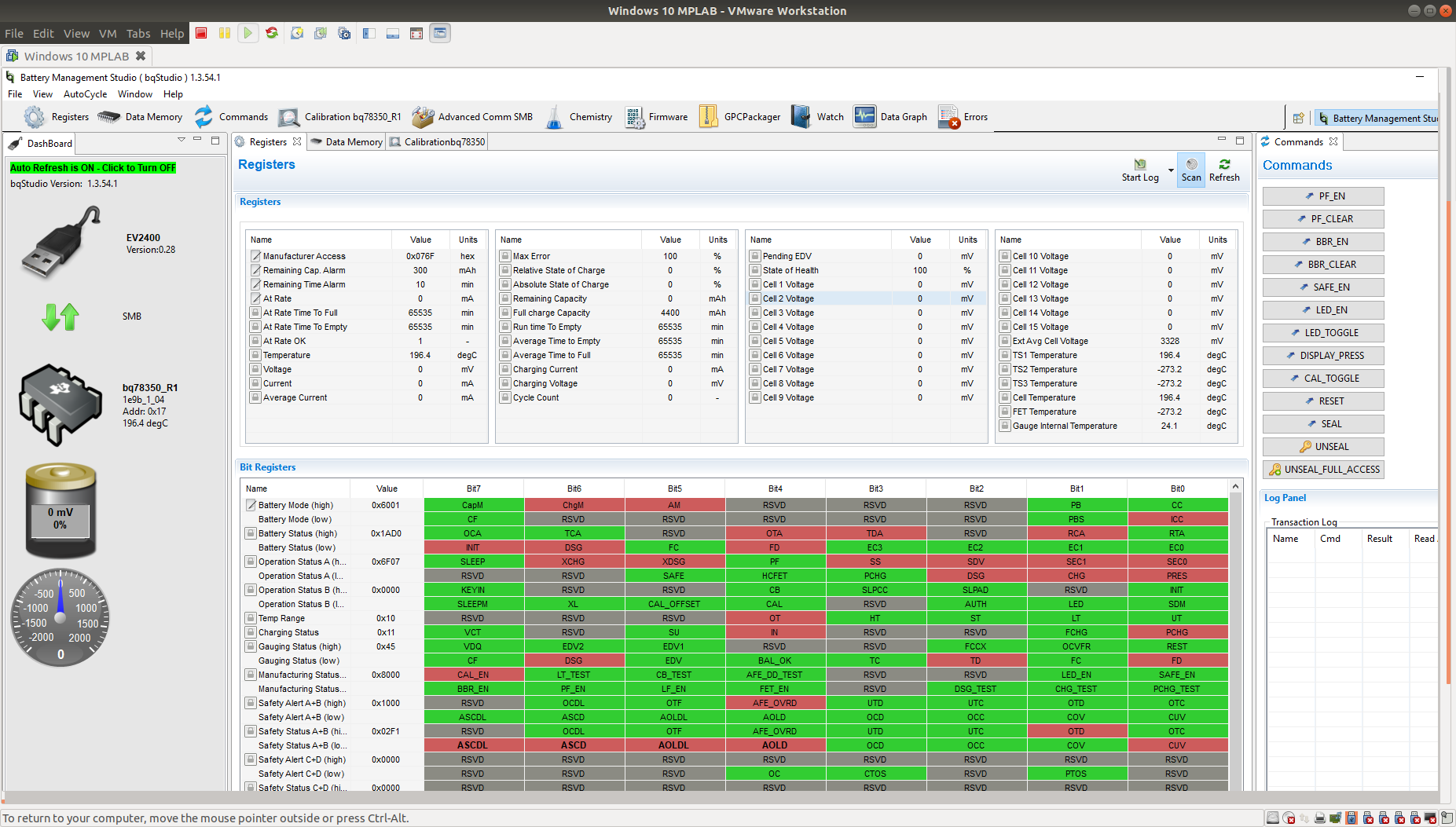
I've got both bqStudio and the BQ769X0 Evaluation Software application installed. I'm testing an 8 cell battery, so have followed the documented instructions and removed the required resistors (R28,R38,R23,R33) and shorted the AFE inputs VC4 to VC3 and VC9 to VC8. Both bqStudio and the Evaluation program start ok. The problem I have encountered is that the cell voltages are not displayed in the bqStudio, however, they are displayed correctly when I run the BQ769X0 Evaluation Software. I've attached a screenshot from both applications which shows the problem.
I suspect I have some bqStudio configuration problem, but can's find any documentation to help fix this.
Has anyone come across this issue before? Any ideas on what might be wrong here?
Cheers,
Mike
Thanks for the suggestion. I forgot to mention the state of the jumpers in my original post, but can confirm that all 4 jumpers are enabled on J14.
I've attached a photo of the board showing the removed diodes, the shorted cells, and the jumpers in position.
I don't know if this is relevant, but in the documentation for the EVM on p19 it mentions the default configuration of the firmware for the bq78350 is for 3 cells. It goes on to say that 'The device must be configured for operation with other cell counts, this includes basic operation of the EVM.' I haven't carried out any 'cell count' configuration - despite looking through the documentation I can't find any reference on how to do this. The only related(?) step I've done is to set the Ext Average Cell Voltage to 3353mV. This step was successful but it didn't result in the individual cell voltages being displayed.
I've just found out how to configure the bq78350 for 8 cells. For anyone interested, the configuration is done via the Data Memory tab of the bqStudio. Under Settings, select the AFE Cell Map and then select the cells you have connected. In my case, having an 8 cell battery, the battery cells from 1-8 are connected to input cell connectors 1, 2, 3, 5, 6, 7, 8, 10 (as per the bq76930 documentation). This results in the map settings value of 0x02f7. Attached is a picture of the screen and my new settings.
However, this has NOT resolved my original issue, namely the cell voltages are not being displayed when I run the EVM in the gauge mode.
Hi Matt
I'm attaching a few screen shots of the registers because they keep changing.
From what I can tell, this is what they are doing.
Safety Alert A+B (High) is toggling between 0x0000 and 0x10000.
Safety Status A+B (High) is toggling between 0x12f1, 0x02f1 0x02a1, and 0x0251.
I tried the RESET button and it returned a result value of N/A - not sure if this is what you expected. Regardless, this, and the subsequent Refresh did not fix the issue.
Hi Matt,
You're correct in that I did use the 'LT_RESET' button, but I then found the 'RESET' button a bit later.
I've tried the sequence you suggested again, but still having the same issue.
I've attached screenshots showing the steps I took - perhaps one of these will help show what is going wrong.
I might be mistaken, but it seemed that the 'RESET' only took effect after I had pressed 'UNSEAL' - is the chip normally in a sealed state?
Once 'RESET' had occurred, the AFE Cell map was empty.
I then set the cells as shown in the following screen shot.
The new cell settings were written to DF using the 'Write_All' button, and I then checked that they had been successfully stored by reloading all settings.
I then calibrated the gauge, setting the average cell voltage to 3.328V.
In the Registers window, I pressed Refresh (and also had rebooted the board previously), but again, no cell voltages displayed.