This thread has been locked.

If you have a related question, please click the "Ask a related question" button in the top right corner. The newly created question will be automatically linked to this question.

TPS62130 broken frequently

Other Parts Discussed in Thread: TPS62130, TPS8268105, TLV62130

Dear members,

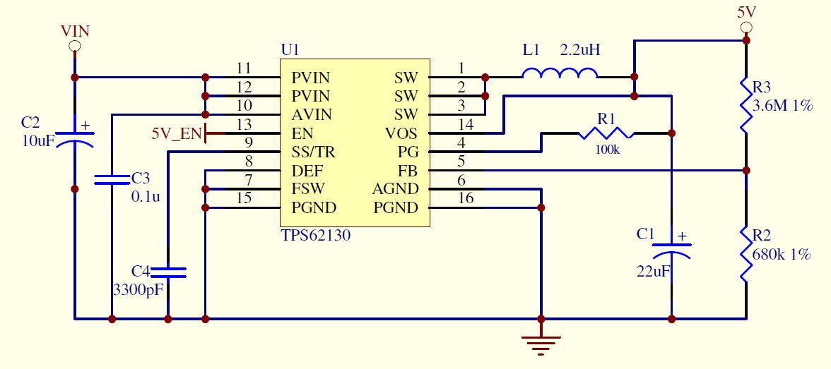
I am designing a power circuit of converting 12V to 5 V

and I found TPS62130 broken for several times.

With the attached schematic, I can get 5 V output at first.

After a few hours, TPS62130 stop functioning and output voltage dropped to 0 V.

However, after I replaced the broken one with a new TPS62130,

the circuit can function again.

Here are more conditions which I can provide about the situation:

  • output current is within 2.5 A
  • Instead of ceramic capacitors, I have used tant capacitor for 22uF output capacitor.
  • there is no short circuit (neither before nor after TPS62130 broken)

Did I made any mistakes on the schematic design?

I am looking forward to any replies and suggestions to improve the circuit performance.

Thank you.

Regards

  • Hi Gordon,

    thanks for sharing schematic and layout.

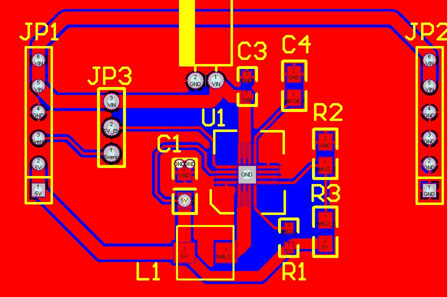
    I think that layout can be slightly improved in this case. I recommend to follow layout recommendation from datasheet, page 27, figure 50.
    There is article which describes step by step layout od the step down converter: www.ti.com/.../slyt614.pdf
    Especially pay attention to proper layout of the trace for VOS pin.

    I don't see reference of the input capacitor C2. Is it tantalum cap?
    We recommend to use ceramic capacitors (input and output) because of high frequency characteristics of these caps. I would recommend to check/compare high frequency characteristics of selected capacitors vs. recommended ceramic cap.

    Values of the feedback resistors are little bit high. Recommendation for feedback resistor is in datasheet, page 13.

    What is the input voltage range of the application?
    What is the end application?

    Best regards

    Lubomir Fenic
  • Thanks for the reply Lubomir.

    The input capacitor C2 using is TAJA226K006RNJ.
    I choose tantalum cap as I refer to the blog below written by TI employee.
    e2e.ti.com/.../what-is-that-giant-tantalum-cap-on-the-input-of-the-evm

    The Input Voltage range is 11.7-12.2 V and should be stable

    One more question to ask:

    Does it matter if I connect the power source of 12V directly to Vin and Enable ?

    Will it cause any voltage overshoots related to “hot-plugging” (which is described in the above blog as well)?


    Finally, I would like to describe the situation when I find the chip is borken.
    I used a loading of around 0.53 A for Vout in order to test TPS62130.
    It was fine before and after I connected the PCB with loading.
    However, after I turn OFF the 12 V power In, the chip can't function anymore after I turn ON the power IN again.

    Please advice for the solution.

  • Hi Gordon,

    you are right, there is tantalum capacitor but there is higher value to attenuate voltage spike during hot-plugins.

    The small input capacitor is placed directly on the module TPS8268105.

    So you have input cap but the value of the tantalum cap can be higher in this case. What is missing in your application is ceramic cap according to the datasheet recommendation page 15.

    It seems that your design is copy of our EVM:

    http://www.ti.com/lit/ug/slvu437a/slvu437a.pdf

    Maybe it is worth to order it and you can save time with re-layout of PCB. Unfortunately PCB layout has to be improved.

    If you connect power supply directly to input cap you are probably using long cables. These cables has inductance which can cause high voltage spike during hot-plugging.

    Best regards

    Lubomir Fenic

  • Lubomir,

    If you read the forums, you will find that this is actually a common and problematic issue with the TPS621XX and TLV621XX series.  We went through probably 20 of these regulators that all mysteriously stopped working.  Some would last a few weeks, others a few months, but they would all eventually die.

    It would be nice if TI would do just a little investigation into this, as I'm sure it is something that could be fixed, and not that hard to reproduce, given time.  These regulators have great specifications, they are just too unreliable to put in a product.

    Good luck with your layout, but I think you'll find that no matter what you do, you'll end up with the same results.  I would recommend looking at another part.

    Here is the link to a related issue we had with the TLV62130 part.

    https://e2e.ti.com/support/power_management/non-isolated_dcdc/f/196/p/418004/1516345

    -Justin

  • Yes, as applications engineers it is our job to assist customers with their applications. This is a very popular device family and used by many many customers. Being so popular, there are many questions, issues, unique configurations being discussed here on E2E.

    I think this present thread is pretty clear: the layout of the input capacitor is poor and the choice of tantalum capacitors with their higher ESR does not meet the data sheet requirement to use ceramics. Especially with modern power supplies switching at high frequencies, it is critical to follow the guidelines outlined in the manual for the chosen device.

    On your thread from last year, I'm happy to continue debugging that with you but need to see some waveforms of what is happening to the device. For sure, you can't just connect a 17V rated device to a car battery and expect it to work fine, since the car battery has well known voltage excursions. A circuit like this should be used to protect such lower voltage devices: http://www.ti.com/tool/PMP9757
  • Thanks for the reply, Chris.

    Although the original intent was to connect to a car battery, the TLV62130 has also 'died' many times just sitting, operating with no significant load transients in a lab environment.  A lab environment and board environment in which we have never had a single other regulator, linear or switching, have any issues ever.  At first, we thought these random 'spontaneous death' issues must have been caused by a quick short circuit that we somehow missed (although technically, the 62130 is supposed to be able to handle one).  This is what prompted us to perform the forced short circuit testing in the other thread, which clearly and quickly causes the 62130 to fail, often in a 'burn out'.

    So then we thought, "okay, a short circuit event is unlikely to occur, we'll just live with it's short circuit performance".  But the same random "spontaneous death" issues kept occurring.  These are less easy to reproduce, because they happen randomly after the regulator will have often been working for weeks.  I would also note that we added circuit protection just in case our lab power supply somehow sent out some transient that was never captured by our scope (or caused any problem with any other part ever).  We put a 13V TVS diode before the regulator input.

    I've sent you waveforms before.  What you're asking for is waveforms of switch current which requires a $3000 DC current probe.  Forgive me if that's not in our budget to help solve a problem which I firmly believe is not on our end.  Additionally, it would be near impossible to capture any signal in the case of the "spontaneous death", only in the "short circuit burnout".  We've already had to spend a lot of resources to re-evaluate other regulators and cram them into our design since they are lower switching frequency which require much larger inductors.

    I genuinely hope someone at TI takes the initiative to do some basic testing, in the off-chance that a customer, whose simple test board schematic and layout has been shared, might have found an issue that could be a real problem.  It cost us time and money to design to and away from the 62130, and we gave it every opportunity to succeed, but it always failed after some period of time.  I would even consider returning to the 62130 in the future, if there were some explanation as to why it failed so many times, and what has changed to fix that.  Or maybe the -Q1 has some redesigned circuitry that eliminates this issue (since it is listed as "automotive qualified" all over the spec sheet).

    My apologies if my rant comes off as frustrated, because I am.  It is just so hard to believe that no others of your many many customers have these issues.  If you do find any issues that would be solved by a different version of the part, please let me know.  If not, that's fine too.  If you want to further the conversation in a different thread, let me know.

    -Justin

  • Yes, we should continue discussing your circuit on your other thread.