This thread has been locked.

If you have a related question, please click the "Ask a related question" button in the top right corner. The newly created question will be automatically linked to this question.

TDA4VM: CPSW2G PHY-less between two TDA4 SOMs (Linux)

Part Number: TDA4VM
Other Parts Discussed in Thread: SYSCONFIG

Our custom design connects the MCU_RGMII1 interfaces of two TDA4 SOMs directly together using a buffer chip and board-to-board connectors. The signals are crossed-over (SOM1 TX <-> SOM2 RX), and I've configured Linux for fixed-link mode:

&cpsw_port1 {
	phy-mode = "rgmii";
	fixed-link {
		speed = <100>;
		full-duplex;
	};
};

And confirmed the correct pinmux:

	mcu_cpsw_pins_default: mcu_cpsw_pins_default {
		pinctrl-single,pins = <
			J721E_WKUP_IOPAD(0x0058, PIN_OUTPUT | DRV_STR_1, 0) /* MCU_RGMII1_TX_CTL */
			J721E_WKUP_IOPAD(0x005c, PIN_INPUT, 0) /* MCU_RGMII1_RX_CTL */
			J721E_WKUP_IOPAD(0x0060, PIN_OUTPUT | DRV_STR_1, 0) /* MCU_RGMII1_TD3 */
			J721E_WKUP_IOPAD(0x0064, PIN_OUTPUT | DRV_STR_1, 0) /* MCU_RGMII1_TD2 */
			J721E_WKUP_IOPAD(0x0068, PIN_OUTPUT | DRV_STR_1, 0) /* MCU_RGMII1_TD1 */
			J721E_WKUP_IOPAD(0x006c, PIN_OUTPUT | DRV_STR_1, 0) /* MCU_RGMII1_TD0 */
			J721E_WKUP_IOPAD(0x0078, PIN_INPUT, 0) /* MCU_RGMII1_RD3 */
			J721E_WKUP_IOPAD(0x007c, PIN_INPUT, 0) /* MCU_RGMII1_RD2 */
			J721E_WKUP_IOPAD(0x0080, PIN_INPUT, 0) /* MCU_RGMII1_RD1 */
			J721E_WKUP_IOPAD(0x0084, PIN_INPUT, 0) /* MCU_RGMII1_RD0 */
			J721E_WKUP_IOPAD(0x0070, PIN_INPUT | DRV_STR_1, 0) /* MCU_RGMII1_TXC */
			J721E_WKUP_IOPAD(0x0074, PIN_INPUT, 0) /* MCU_RGMII1_RXC */
		>;
	};

Output from ethtool shows that the interface is up and attempting to transmit, but is not receiving (or even dropping) packets from the remote side: (same result on from both SOMs)

NIC statistics:
     p0_rx_good_frames: 47
     p0_rx_broadcast_frames: 23
     p0_rx_multicast_frames: 24
     p0_rx_crc_errors: 0
     p0_rx_oversized_frames: 0
     p0_rx_undersized_frames: 0
     p0_ale_drop: 0
     p0_ale_overrun_drop: 0
     p0_rx_octets: 10870
     p0_tx_good_frames: 0
     p0_tx_broadcast_frames: 0
     p0_tx_multicast_frames: 0
     p0_tx_octets: 0
     p0_tx_64B_frames: 2
     p0_tx_65_to_127B_frames: 14
     p0_tx_128_to_255B_frames: 8
     p0_tx_256_to_511B_frames: 23
     p0_tx_512_to_1023B_frames: 0
     p0_tx_1024B_frames: 0
     p0_net_octets: 10870
     p0_rx_bottom_fifo_drop: 0
     p0_rx_port_mask_drop: 0
     p0_rx_top_fifo_drop: 0
     p0_ale_rate_limit_drop: 0
     p0_ale_vid_ingress_drop: 0
     p0_ale_da_eq_sa_drop: 0
     p0_ale_block_drop: 0
     p0_ale_secure_drop: 0
     p0_ale_auth_drop: 0
     p0_ale_unknown_ucast: 0
     p0_ale_unknown_ucast_bytes: 0
     p0_ale_unknown_mcast: 0
     p0_ale_unknown_mcast_bytes: 0
     p0_ale_unknown_bcast: 0
     p0_ale_unknown_bcast_bytes: 0
     p0_ale_pol_match: 0
     p0_ale_pol_match_red: 0
     p0_ale_pol_match_yellow: 0
     p0_ale_mcast_sa_drop: 0
     p0_ale_dual_vlan_drop: 0
     p0_ale_len_err_drop: 0
     p0_ale_ip_next_hdr_drop: 0
     p0_ale_ipv4_frag_drop: 0
     p0_tx_mem_protect_err: 0
     p0_tx_pri0: 0
     p0_tx_pri1: 0
     p0_tx_pri2: 0
     p0_tx_pri3: 0
     p0_tx_pri4: 0
     p0_tx_pri5: 0
     p0_tx_pri6: 0
     p0_tx_pri7: 0
     p0_tx_pri0_bcnt: 0
     p0_tx_pri1_bcnt: 0
     p0_tx_pri2_bcnt: 0
     p0_tx_pri3_bcnt: 0
     p0_tx_pri4_bcnt: 0
     p0_tx_pri5_bcnt: 0
     p0_tx_pri6_bcnt: 0
     p0_tx_pri7_bcnt: 0
     p0_tx_pri0_drop: 0
     p0_tx_pri1_drop: 0
     p0_tx_pri2_drop: 0
     p0_tx_pri3_drop: 0
     p0_tx_pri4_drop: 0
     p0_tx_pri5_drop: 0
     p0_tx_pri6_drop: 0
     p0_tx_pri7_drop: 0
     p0_tx_pri0_drop_bcnt: 0
     p0_tx_pri1_drop_bcnt: 0
     p0_tx_pri2_drop_bcnt: 0
     p0_tx_pri3_drop_bcnt: 0
     p0_tx_pri4_drop_bcnt: 0
     p0_tx_pri5_drop_bcnt: 0
     p0_tx_pri6_drop_bcnt: 0
     p0_tx_pri7_drop_bcnt: 0
     rx_good_frames: 0
     rx_broadcast_frames: 0
     rx_multicast_frames: 0
     rx_pause_frames: 0
     rx_crc_errors: 0
     rx_align_code_errors: 0
     rx_oversized_frames: 0
     rx_jabber_frames: 0
     rx_undersized_frames: 0
     rx_fragments: 1
     ale_drop: 0
     ale_overrun_drop: 0
     rx_octets: 0
     tx_good_frames: 47
     tx_broadcast_frames: 23
     tx_multicast_frames: 24
     tx_pause_frames: 0
     tx_deferred_frames: 0
     tx_collision_frames: 0
     tx_single_coll_frames: 0
     tx_mult_coll_frames: 0
     tx_excessive_collisions: 0
     tx_late_collisions: 0
     rx_ipg_error: 0
     tx_carrier_sense_errors: 0
     tx_octets: 10870
     tx_64B_frames: 2
     tx_65_to_127B_frames: 14
     tx_128_to_255B_frames: 8
     tx_256_to_511B_frames: 23
     tx_512_to_1023B_frames: 0
     tx_1024B_frames: 0
     net_octets: 10873
     rx_bottom_fifo_drop: 0
     rx_port_mask_drop: 0
     rx_top_fifo_drop: 0
     ale_rate_limit_drop: 0
     ale_vid_ingress_drop: 0
     ale_da_eq_sa_drop: 0
     ale_block_drop: 0
     ale_secure_drop: 0
     ale_auth_drop: 0
     ale_unknown_ucast: 0
     ale_unknown_ucast_bytes: 0
     ale_unknown_mcast: 0
     ale_unknown_mcast_bytes: 0
     ale_unknown_bcast: 0
     ale_unknown_bcast_bytes: 0
     ale_pol_match: 0
     ale_pol_match_red: 0
     ale_pol_match_yellow: 0
     ale_mcast_sa_drop: 0
     ale_dual_vlan_drop: 0
     ale_len_err_drop: 0
     ale_ip_next_hdr_drop: 0
     ale_ipv4_frag_drop: 0
     iet_rx_assembly_err: 0
     iet_rx_assembly_ok: 0
     iet_rx_smd_err: 653
     iet_rx_frag: 0
     iet_tx_hold: 0
     iet_tx_frag: 0
     tx_mem_protect_err: 0
     tx_pri0: 47
     tx_pri1: 0
     tx_pri2: 0
     tx_pri3: 0
     tx_pri4: 0
     tx_pri5: 0
     tx_pri6: 0
     tx_pri7: 0
     tx_pri0_bcnt: 10870
     tx_pri1_bcnt: 0
     tx_pri2_bcnt: 0
     tx_pri3_bcnt: 0
     tx_pri4_bcnt: 0
     tx_pri5_bcnt: 0
     tx_pri6_bcnt: 0
     tx_pri7_bcnt: 0
     tx_pri0_drop: 0
     tx_pri1_drop: 0
     tx_pri2_drop: 0
     tx_pri3_drop: 0
     tx_pri4_drop: 0
     tx_pri5_drop: 0
     tx_pri6_drop: 0
     tx_pri7_drop: 0
     tx_pri0_drop_bcnt: 0
     tx_pri1_drop_bcnt: 0
     tx_pri2_drop_bcnt: 0
     tx_pri3_drop_bcnt: 0
     tx_pri4_drop_bcnt: 0
     tx_pri5_drop_bcnt: 0
     tx_pri6_drop_bcnt: 0
     tx_pri7_drop_bcnt: 0

And some relevant CPSW registers:

CTRL_MMR0 MCU_ENET_CTRL
0x40f04040 = 0x00000002
CPSW0_NUSS RGMII STATUS
0x46000018 = 0x00000000
CPSW0_NUSS PN_MAC_CONTROL
0x46022330 = 0x00000021
CPSW0_NUSS PN_MAC_STATUS
0x46022334 = 0xF0000008
STAT_0 (RXGOOD, TXGOOD)
0x4603a000 = 0x00000036
0x4603a034 = 0x00000000
STAT_1 (RXGOOD, TXGOOD)
0x4603a200 = 0x00000000
0x4603a234 = 0x00000036
STAT_0 (RXGOOD, TXGOOD)
0x4603a000 = 0x00000036
0x4603a034 = 0x00000000
STAT_1 (RXGOOD, TXGOOD)
0x4603a200 = 0x00000000
0x4603a234 = 0x00000036

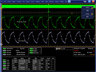
Besides the above, I've also confirmed with a scope that one SOM's RXC input is getting the remote SOM's TXC ouput, and the clock is the expected value for the above config: 100Mbps -> 25MHz TXC. (Ideally we want 1G, but I'm using 100M so I can use one of our cheap scopes at my desk)

I'm unsure what is wrong, though I am somewhat concerned about register CPSW_SS_RGMII_STATUS_REG (0x46000018) being 0x0?

Where next should I investigate?

  • Hi,

    The fixed link patch looks correct.

    Can you tell me

    1. Which SDK are you using ?

    2. Can you share your DT changes (as a patch), for both Uboot and Linux.

    3. Did you use the SysConfig tool from TI for pinmuxing ?

    4. If your board design was reviewed within TI ?

    Regards

    Vineet

  • 1) PSDK 7.0 (Linux 5.4.40)

    2) I'll see if I can scrub customer info from the Linux DT. We don't need this functionality under Uboot: Would it have any bearing on Linux?

    3) Yes we did

    4) I'm not aware if it was or wasn't

  • We caught a minor error in our HW that is now resolved (bus isolation chip was clipping signal), but still no success with the link.

    There is one small change however, it seems that I'm getting a steady stream of "IET Receive SMD" errors. This confuses me, as IET does not appear to be configured on either end of the link? (CPSW_CONTROL_REG 0x0C020004 = 0xE00E, bit 17 is not set)

  • That  "IET" stat can be ignored, it was not disabled when not in IET mode. It will be fixed in future devices.

  • What clock rates are you running the RGMII at?

    I am assuming you have the

    RXC <- remote TXC

    RXD <- remote TXD

    RX_CTL <- remote TX_CTL

    TXC -> remote RXC

    TXD -> remote RXD

    TX_CTL -> remote RX_CTL

    The clock would be 125Mhz for 1G mode

    What is the Enet_Pn_Mac_Control - (0x330 + 0x1000 + 0x1000n) register value?

    Is this a J7ES device?

    Which ports are being directly connected?

  • 2x J7ES devices, connecting the external ports of MCU_CPSW0 (aka CPSW2G) to each other. Signal mappings match what you've written above Thumbsup

    PN_MAC_CONTROL on both sides is 0x21. Here's the registers I'm currently monitoring:

    "Left" board:

    CTRL_MMR0 MCU_ENET_CTRL
    0x40f04040 = 0x00000002
    CPSW0_NUSS RGMII STATUS
    0x46000018 = 0x00000000
    CPSW0_NUSS PN_MAC_CONTROL
    0x46022330 = 0x00000021
    CPSW0_NUSS PN_MAC_STATUS
    0x46022334 = 0xF0000008
    STAT_0 (RXGOOD, TXGOOD)
    0x4603a000 = 0x0000002A
    0x4603a034 = 0x00000000
    STAT_1 (RXGOOD, TXGOOD)
    0x4603a200 = 0x00000000
    0x4603a234 = 0x0000002A

    "Right" board:

    CTRL_MMR0 MCU_ENET_CTRL
    0x40f04040 = 0x00000002
    CPSW0_NUSS RGMII STATUS
    0x46000018 = 0x00000000
    CPSW0_NUSS PN_MAC_CONTROL
    0x46022330 = 0x00000021
    CPSW0_NUSS PN_MAC_STATUS
    0x46022334 = 0xF0000008
    CPSW0_NUSS ALE PORTCTL0_y
    0x4603e040 = 0x00000013
    0x4603e044 = 0x00000813
    STAT_0 (RXGOOD, TXGOOD)
    0x4603a000 = 0x00000029
    0x4603a034 = 0x00000000
    STAT_1 (RXGOOD, TXGOOD)
    0x4603a200 = 0x00000000
    0x4603a234 = 0x00000029
    

  • Hi Josh,

    Register values look ok, although bit 7 (gigabit mode) of CPSW_PN_MAC_CONTROL_REG is not set for both boards. I don't know what impact this will have.

    Have you tried to connect a scope and see the signal ?

    Regards

    Vineet

  • Sorry, I forgot I had the speed limited to 100Mbit on both sides so that I could use the scope at my desk (50MHz, 1GS/s). At that speed, I have seen individual signals & the clock (25MHz at 100Mbit), but I don't currently have a way to observe more than signal at a time.

    Here's the register dump for "left" at 1Gbit:

    CTRL_MMR0 MCU_ENET_CTRL
    0x40f04040 = 0x00000002
    CPSW0_NUSS RGMII STATUS
    0x46000018 = 0x00000000
    CPSW0_NUSS PN_MAC_CONTROL
    0x46022330 = 0x000000A1
    CPSW0_NUSS PN_MAC_STATUS
    0x46022334 = 0xF0000018
    STAT_0 (RXGOOD, TXGOOD)
    0x4603a000 = 0x00000023
    0x4603a034 = 0x00000000
    STAT_1 (RXGOOD, TXGOOD)
    0x4603a200 = 0x00000000
    0x4603a234 = 0x00000023
    

    And "right":

    CTRL_MMR0 MCU_ENET_CTRL
    0x40f04040 = 0x00000002
    CPSW0_NUSS RGMII STATUS
    0x46000018 = 0x00000000
    CPSW0_NUSS PN_MAC_CONTROL
    0x46022330 = 0x000000A1
    CPSW0_NUSS PN_MAC_STATUS
    0x46022334 = 0xF0000018
    CPSW0_NUSS ALE PORTCTL0_y
    0x4603e040 = 0x00000013
    0x4603e044 = 0x00000813
    STAT_0 (RXGOOD, TXGOOD)
    0x4603a000 = 0x0000001E
    0x4603a034 = 0x00000000
    STAT_1 (RXGOOD, TXGOOD)
    0x4603a200 = 0x00000000
    0x4603a234 = 0x0000001E
    

    I'm not 100% clear on "rgmii-id" vs "rgmii": For PHY-less mode, I should be using the internal delay mode (rgmii-id) correct?

  • The values match with the EVM

    >For PHY-less mode, I should be using the internal delay mode (rgmii-id) correct?

    Yes, that's correct.

    I will review this internally but at a top level this looks correct.

    Next step would be to check the scope output for all the lines and clock. Has the HW design been reviewed by someone within TI ?

    Regards

    Vineet

  • Is there any reason why this wouldn't work at 10 or 100Mbit? (To make it easier to scope and help rule-out signal integrity issues)

    I don't believe this portion of the design has been reviewed by TI.

  • No, you should be able to check at 100M as well.

    Regards

    Vineet

  • Since you are in force mode, you cannot run in 10Mbps mode, only 1Gbps/100Mbps are available via the Gig bit in the MAC_CONTROL.

    PN_MAC_CONTROL of 0x000000A1 is Gig mode and requires a 125Mhz clock, the IP requires a 250Mhz clock internally.

    It should be 0x00000021 for 100Mbps mode.

  • Why is the TXC pin defined as an input?

    "J721E_WKUP_IOPAD(0x0070, PIN_INPUT | DRV_STR_1, 0) /* MCU_RGMII1_TXC */"

    We would expect the TXC pin to be an output.

  • Conclusions from yesterday's debug:

    1. Clock looks correct.

    2. Rx and Tx pins toggling with data

    3. Packets are being received on the interface (binning counters are going up) but they are not counted as good frames, indicating some kind of error.

    4. SMD errors are correlated to the packets being received.

    5. Need to review MAC 2 MAC schematics to rule out any issues.

    Hi Josh,

    Can you answer question from Denis on pinmux ?

    Regards

    Vineet

  • :

    Pinmux: I had noticed the strange pinmux before, but at the time I discounted it as a problem: PIN_INPUT resolves to INPUT_EN|PULL_DISABLE --> (1<<18|1<<16), which means that TX_DIS (1<<21) is 0. The above was generated from the sysconfig tool, and I'm about to test changing it to PIN_OUTPUT (PULL_DISABLE --> 1<<16).

    10Mbps: Understood, I will continue debugging with only 100Mbit or 1Gbit.

  • The TXC signal at 100Mbit looks pretty bad, and I've been unable to affect it much using drive-strength...

    Gray: At "right" board's TXC before FET switch
    Green: "left" board's RXC at SOM to baseboard connector (J7 SOM side)

    TXC vs RXC

    Teal: "left" board's RXC, DRV=0
    Purple: "left board's RXC, DRV=3

    DRV=0 vs DRV=1

    I'm worried that our traces are simply too long for RGMII to traverse :-(

  • Note DRV=3 is actually reserved.  The strongest drive should be DRV=1.

  • I agree the waveform shown in purple appears to be impacted from loading.

  • We've reworked one of the two J7 SOMs to replace the 22ohm resistors with 0ohm and it has cleaned up the received signal at the far end, but still not receiving any packets. Does the RGMII need to be functioning in both directions before any packets are passed? Or will one direction suffice?

  • As long as you have programmed the interface in Full Duplex mode, the RGMII can operate in a single direction.

    Have you verified the connectivity of the RXDV and RXD[3:0] line are correctly connected to the TXEN and TXD[3:0] respectively?

  • I've finally gotten back to this: We appear to have made an error in the pin assignment between the two carrier boards resulting in 3->0, 2->1, 1->2, 0->3 in both TD and RD directions. I don't suppose there's a way to remap the bits in the RGMII receiver?

  • That would indeed cause receive issues!

    There is no ability to swap the pins internally.