This thread has been locked.

If you have a related question, please click the "Ask a related question" button in the top right corner. The newly created question will be automatically linked to this question.

TMDS64GPEVM: connect problem

Part Number: TMDS64GPEVM

Hi team,

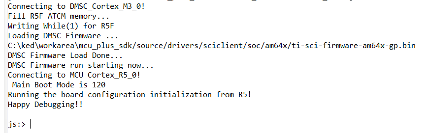
I could have connected r5f before.
DDR initialization: run DDR initialization from the gel menu as shown below. I'm not sure if the initialization is finished, so I turn off the power and can't connect it later.

Please help to analyze it.thanks a lot.

Best regards,

  • Are you saying you could connect to R5F previously but after running the DDR initialization you can no longer connect to the R5F, even after power reset?

  • Hi Arnon,

    yes,This is the case.

    thank you.

  • Hi Arnon,

    Any updata?

    Thank you.

  • Hi Zhonghui, sorry, no update yet.  Will try to get an update as soon as possible.

  • Hello,

    Could you please share which boot mode the EVM is in? 

    Do you still observe this error after running the load_dmsc.js script as described in the section "Run the SOC Initialization Script" of the EVM Setup guide

    Regards,
    Sahin

  • Hi Sahin,

    Thank you for your help.

    1.I can't connect to CORTEX. I need to refresh the firmware.

    I use the CCS provided by the official website to install, how should I use these.

    ./ccs/ccs_base/emulation/gel/AM64x/CPU_reset.gel
    ./ccs/ccs_base/emulation/gel/AM64x/AM64_common/registerpoke.gel
    ./ccs/ccs_base/emulation/gel/AM64x/AM64_common/AM64_common.gel
    ./ccs/ccs_base/emulation/gel/AM64x/AM64_PLL/AM64_PLL_OFC1.gel
    ./ccs/ccs_base/emulation/gel/AM64x/AM64_PLL/25MHz_HFOSC/AM64_PLL_PARAMS_UC_1_2.gel
    ./ccs/ccs_base/emulation/gel/AM64x/AM64_PLL/25MHz_HFOSC/AM64_PLL_PARAMS_UC_1_1_1.gel
    ./ccs/ccs_base/emulation/gel/AM64x/AM64_PLL/25MHz_HFOSC/AM64_PLL_PARAMS_OFC1.gel
    ./ccs/ccs_base/emulation/gel/AM64x/AM64_PLL/25MHz_HFOSC/AM64_PLL_PARAMS_UC_1_3.gel
    ./ccs/ccs_base/emulation/gel/AM64x/AM64_PLL/AM64_PLL_DDR_configurations.gel
    ./ccs/ccs_base/emulation/gel/AM64x/AM64_PLL/AM64_PLL_bypass.gel
    ./ccs/ccs_base/emulation/gel/AM64x/AM64_PLL/AM64_PLL_non_UC_configurations.gel
    ./ccs/ccs_base/emulation/gel/AM64x/AM64_PLL/AM64_PLL_UC_1_1_1.gel
    ./ccs/ccs_base/emulation/gel/AM64x/AM64_PLL/AM64_PLL_UC_1_2.gel
    ./ccs/ccs_base/emulation/gel/AM64x/AM64_PLL/AM64_PLL_MMR.gel
    ./ccs/ccs_base/emulation/gel/AM64x/AM64_PLL/AM64_PLL_UC_1_3.gel
    ./ccs/ccs_base/emulation/gel/AM64x/AM64_PLL/AM64_PLL.gel
    ./ccs/ccs_base/emulation/gel/AM64x/AM64_DDRSS/AM64x_GP_EVM.gel
    ./ccs/ccs_base/emulation/gel/AM64x/AM64_DDRSS/AM64_DDRSS_Config.gel
    ./ccs/ccs_base/emulation/gel/AM64x/AM64_DDRSS/AM64_DDRSS_RegDump.gel
    ./ccs/ccs_base/emulation/gel/AM64x/AM64_DDRSS/AddrMapCheck.gel
    ./ccs/ccs_base/emulation/gel/AM64x/AM64_DDRSS/AM64x-DDR4-1333MTs.gel
    ./ccs/ccs_base/emulation/gel/AM64x/AM64_DDRSS/AM64x-DDR4-1600MTs.gel
    ./ccs/ccs_base/emulation/gel/AM64x/AM64_DDRSS/AM64_DDRSS_addr_map_sfr_offs_ew_16bit.gel
    ./ccs/ccs_base/emulation/gel/AM64x/AM64_PSC/AM64_PSC_UC_1_2.gel
    ./ccs/ccs_base/emulation/gel/AM64x/AM64_PSC/AM64_PSC_UC_1_1_1.gel
    ./ccs/ccs_base/emulation/gel/AM64x/AM64_PSC/AM64_PSC.gel
    ./ccs/ccs_base/emulation/gel/AM64x/AM64_PSC/AM64_PSC_UC_1_3.gel
    ./ccs/ccs_base/emulation/gel/AM64x/AM64x.gel

    2.There is another problem
    There is a problem with the file system process provided for compiling am644x,
    MACHINE= am64x-evm
    There is no related .Conf files under meta ti/conf/machine.

    Best regards,

  • Hi Sahin,

    Thank you for your help.

    Any update?

    Best regards,

  • Hello,

    Could you please try these steps and let us know your results?

    1. Set EVM to NO BOOT mode:
    2. Power on the EVM
    3. In CCS, launch the target configuration for the AM64x_EVM
    4. Once launched, open the CCS scripting console (View -> Scripting Console)
    5. Run the DMSC init script in the scripting console:

    You should see the following output. Could you please confirm you see the same?

    At this point you should be able to connect to the CORTEX_R5's and run the DDR initialization script. 

    For #2, could you please share the full log that you see when compiling? 

    Regards,
    Sahin

  • I am facing the same error signature.

    I tried running the js and received this error:

    js:> loadJSFile <scrubbed>/ti/mcu_plus_sdk_am64x_07_03_00_19/tools/ccs_load/am64x/load_dmsc.js
    Connecting to DMSC_Cortex_M3_0!
    Error connecting to the target: emulation failure occurred (<scrubbed>/ti/mcu_plus_sdk_am64x_07_03_00_19/tools/ccs_load/am64x/load_dmsc.js#146)

  • Hi Sahin,

    Thank you for your reply.

    According to your documents, but there is error.

    Error connecting to the target:
    (Error -1170 @ 0x0)
    Unable to access the DAP. Reset the device, and retry the operation. If error persists, confirm configuration, power-cycle the board, and/or try more reliable JTAG settings (e.g. lower TCLK).
    (Emulation package 9.3.0.00058)

    Best Regards,


  • I have the following output from the test connection process.  Maybe this helps?

    [Start: Texas Instruments XDS110 USB Debug Probe]
    
    Execute the command:
    
    %ccs_base%/common/uscif/dbgjtag -f %boarddatafile% -rv -o -S integrity
    
    [Result]
    
    
    -----[Print the board config pathname(s)]------------------------------------
    
    <snip>/.ti/ccs1010/
        0/0/BrdDat/testBoard.dat
    
    -----[Print the reset-command software log-file]-----------------------------
    
    This utility has selected a 100- or 510-class product.
    This utility will load the adapter 'libjioxds110.so'.
    The library build date was 'Jan 31 2021'.
    The library build time was '22:02:59'.
    The library package version is '9.3.0.00042'.
    The library component version is '35.35.0.0'.
    The controller does not use a programmable FPGA.
    The controller has a version number of '5' (0x00000005).
    The controller has an insertion length of '0' (0x00000000).
    This utility will attempt to reset the controller.
    This utility has successfully reset the controller.
    
    -----[Print the reset-command hardware log-file]-----------------------------
    
    The scan-path will be reset by toggling the JTAG TRST signal.
    The controller is the XDS110 with USB interface.
    The link from controller to target is direct (without cable).
    The software is configured for XDS110 features.
    The controller cannot monitor the value on the EMU[0] pin.
    The controller cannot monitor the value on the EMU[1] pin.
    The controller cannot control the timing on output pins.
    The controller cannot control the timing on input pins.
    The scan-path link-delay has been set to exactly '0' (0x0000).
    
    -----[An error has occurred and this utility has aborted]--------------------
    
    This error is generated by TI's USCIF driver or utilities.
    
    The value is '-233' (0xffffff17).
    The title is 'SC_ERR_PATH_BROKEN'.
    
    The explanation is:
    The JTAG IR and DR scan-paths cannot circulate bits, they may be broken.
    An attempt to scan the JTAG scan-path has failed.
    The target's JTAG scan-path appears to be broken
    with a stuck-at-ones or stuck-at-zero fault.
    
    [End: Texas Instruments XDS110 USB Debug Probe]
        
    
  • Nevermind the last response.  First thing in the morning and I forgot to switch the board on Stuck out tongue

    The output is now (but I still can't debug):

    [Start: Texas Instruments XDS110 USB Debug Probe]
    
    Execute the command:
    
    %ccs_base%/common/uscif/dbgjtag -f %boarddatafile% -rv -o -S integrity
    
    [Result]
    
    
    -----[Print the board config pathname(s)]------------------------------------
    
    snip/.ti/ccs1010/
        0/0/BrdDat/testBoard.dat
    
    -----[Print the reset-command software log-file]-----------------------------
    
    This utility has selected a 100- or 510-class product.
    This utility will load the adapter 'libjioxds110.so'.
    The library build date was 'Jan 31 2021'.
    The library build time was '22:02:59'.
    The library package version is '9.3.0.00042'.
    The library component version is '35.35.0.0'.
    The controller does not use a programmable FPGA.
    The controller has a version number of '5' (0x00000005).
    The controller has an insertion length of '0' (0x00000000).
    This utility will attempt to reset the controller.
    This utility has successfully reset the controller.
    
    -----[Print the reset-command hardware log-file]-----------------------------
    
    The scan-path will be reset by toggling the JTAG TRST signal.
    The controller is the XDS110 with USB interface.
    The link from controller to target is direct (without cable).
    The software is configured for XDS110 features.
    The controller cannot monitor the value on the EMU[0] pin.
    The controller cannot monitor the value on the EMU[1] pin.
    The controller cannot control the timing on output pins.
    The controller cannot control the timing on input pins.
    The scan-path link-delay has been set to exactly '0' (0x0000).
    
    -----[Perform the Integrity scan-test on the JTAG IR]------------------------
    
    This test will use blocks of 64 32-bit words.
    This test will be applied just once.
    
    Do a test using 0xFFFFFFFF.
    Scan tests: 1, skipped: 0, failed: 0
    Do a test using 0x00000000.
    Scan tests: 2, skipped: 0, failed: 0
    Do a test using 0xFE03E0E2.
    Scan tests: 3, skipped: 0, failed: 0
    Do a test using 0x01FC1F1D.
    Scan tests: 4, skipped: 0, failed: 0
    Do a test using 0x5533CCAA.
    Scan tests: 5, skipped: 0, failed: 0
    Do a test using 0xAACC3355.
    Scan tests: 6, skipped: 0, failed: 0
    All of the values were scanned correctly.
    
    The JTAG IR Integrity scan-test has succeeded.
    
    -----[Perform the Integrity scan-test on the JTAG DR]------------------------
    
    This test will use blocks of 64 32-bit words.
    This test will be applied just once.
    
    Do a test using 0xFFFFFFFF.
    Scan tests: 1, skipped: 0, failed: 0
    Do a test using 0x00000000.
    Scan tests: 2, skipped: 0, failed: 0
    Do a test using 0xFE03E0E2.
    Scan tests: 3, skipped: 0, failed: 0
    Do a test using 0x01FC1F1D.
    Scan tests: 4, skipped: 0, failed: 0
    Do a test using 0x5533CCAA.
    Scan tests: 5, skipped: 0, failed: 0
    Do a test using 0xAACC3355.
    Scan tests: 6, skipped: 0, failed: 0
    All of the values were scanned correctly.
    
    The JTAG DR Integrity scan-test has succeeded.
    
    [End: Texas Instruments XDS110 USB Debug Probe]
    
    
  • Richard,

    The connection test passes so we can rule out issues with the target configuration and emulator. 

    • If you connect to the UART port on the EVM and load the CCS terminal (or any terminal), and power cycle your EVM, what do you see on the terminal window? For steps on setting up the UART terminal, please see: EVM Setup

    • Can you make sure all of the LEDs on the EVM are lit as shown in section 3.3.1 of the EVM User Guide?

    • Can you confirm the EVM is in "NO BOOT" mode?

     Zhonghui,

    Could you please try selecting "Test Connection" as well and share your output? If it passes, please try/confirm the steps above.

    Regards,
    Sahin

  • 1/ I get nothing in the terminal in no-boot mode

    2/ all LEDs are lit properly

    why do you ask to go into NO BOOT mode when the documentation says otherwise?  It says the recommended is OSPI mode?

    dev.ti.com/.../CCS_LAUNCH_PAGE.html

  • It should be in OSPI boot mode when initializing the SOC using the OSPI Flash method, which is the recommended method as it is the most convenient since you don't have to manually run the script after each power cycle.

    There are 3 methods to initializing the SOC:

    1. SOC initialization via OSPI Flash - when using this method you need to be in OSPI boot mode so that the SOC initialization binary runs from Flash on power-up.

    2. SOC initialization via SD card - this method involves running the SOC initialization from an SD card - for this method you need to be in SD boot mode. 

    3. SOC initialization via CCS Scripting Console - in this method you need to be in NO BOOT mode and run the SOC initialization script (load_dmsc.js) from the CCS scripting console.

    I haven't been able to reproduce this issue with my EVM - I need to do some more digging and ask around internally and get back to you. 

    Regards,
    Sahin

  • After launching the target configuration, are you able to connect to the M3 (before running the load DMSC script)?

    Regards,
    Sahin

  • I am unable to connect to any core - R5, M3, M4, A53, PRU.  I receive the same error for all of them.

  • Not sure if this makes any difference but I'm running on Ubuntu 18.04.

  • I wouldn't suspect that to be an issue - Ubuntu 18.04 is supported. 

    Which CCS version are you using? 10.3? 

    Is this a fresh EVM? Have you not been able to connect at all or did this recently start occurring?

    Regards,
    Sahin

  • 1/ CCS version:  Version: 10.2.0.00009

    2/ Fresh. I just started setting up the EVM last week.  I was able to do steps up to and including the SOC initialization here https://dev.ti.com/tirex/explore/content/mcu_plus_sdk_am64x_07_03_00_19/docs/api_guide_am64x/EVM_SETUP_PAGE.html and then the step after (DDR initialization) because I can't connect to the core.

  • You need to use at least v10.3 of CCS - this is the version that added the device support for AM64x. You can install it from here: https://www.ti.com/tool/CCSTUDIO

    This should resolve your issue, but if it doesn't please let me know.

    Regards,
    Sahin

  • New version:  Version: 10.3.1.00003 

    Behavior: same

  • Hi Sahin and Richard,

    Thank you for your help.

    According to your knowledge, noboot EVM is powered on, but it can't be connected;

    UART bootmode starts EVM, after successful burning, then OSPI mode, and the serial output is correct. At this time, all cores cannot be connected

    The problem now is that no matter which mode you are in,  just can't connect.

  • Completely agree with - just stuck.  Usually when something like this happens I go hunting for potentially incorrect jumper settings but it is not clear to me if any jumpers would influence this behavior.

    I know that at least the A53 cores are running - I can login to the booted linux image no problem.  That obviously doesn't help with my need to work with the Cortex-R5 cores though.

  • Hi Richard and Zhonghui,

    This is apparently a known issue with the E2 revisions of the EVM, see section 4.1 of the EVM User Guide: 

    Sorry for the delay in finding this. Please let me know if these suggested workarounds for you.

    Regards,
    Sahin

  • I already followed that instruction and it did not help.

  • Hmm, this is a real head-scratcher. You don't have Linux running on the A53s while trying this right? Linux takes control of the system and can prevent connection to the R5Fs via CCS. When in no boot mode I wouldn't expect this to be an issue though.

    I'm going to discuss this with my colleagues some more and get back to you. 

    Regards,
    Sahin

  • I tried the procedure once more to no avail.

    The only other thing I can think of is I'm using a 12V 5A power brick instead of the named 12V 8A.  But I suppose 8A would be when driving peripherals under load and running at 5A would not cause this behavior. Can you confirm this point as well?

  • Yeah I wouldn't suspect that to cause this behavior but I'll confirm.

    Could you please share which EVM revision you have? The label can be found here: 

    Regards,
    Sahin

  • Also when you go to dev.ti.com, does your EVM get detected? (Make sure your board is connected, powered on, and no CCS target configuration is running)

    Regards,
    Sahin

  • Hello Sahin,

    The photo having the requested information is here.

  • Hello Sahin,

    The board connects successfully.

    Should I try to connect to the R5 through this app? Never used it before.

  • Bummer I guess that's not happening.

  • Thanks for checking. CCS Cloud is not yet supported so indeed building won't work. I wanted to confirm the on-board XDS110 was correctly factory-programmed and it looks like it is.

    While we investigate this internally, do you happen to have a stand-alone debug probe like the XDS110 or XDS200 you could try?

    Regards,
    Sahin

  • I don't have a standalone TI XDS debugger.  I have SEGGER.

    Please let me know the recommended one if we really need it as next step.

    I was going to try the SEGGER on this board but couldn't find information on it or even if it would work.

    EDIT: I looked at the SEGGER option and it looks like I need this adapter to make it work.  So... if SEGGER works I prefer that and just get the adapter.  Otherwise, let me know the optimal XDS debugger.

    EDIT2: I ordered the SEGGER adapter just in case.  Looking forward to other news and if I need the XDS external debugger.

    EDIT3: Looks like I will receive the SEGGER part today - any notes on using it in the context of this board is welcome Slight smile

    www.segger.com/.../

  • I don't have a standalone TI XDS debugger.  I have SEGGER.

    Please let me know the recommended one if we really need it as next step.

    I was going to try the SEGGER on this board but couldn't find information on it or even if it would work.

    EDIT: I looked at the SEGGER option and it looks like I need this adapter to make it work.  So... if SEGGER works I prefer that and just get the adapter.  Otherwise, let me know the optimal XDS debugger.

    EDIT2: I ordered the SEGGER adapter just in case.  Looking forward to other news and if I need the XDS external debugger.

    EDIT3: Looks like I will receive the SEGGER part today - any notes on using it in the context of this board is welcome Slight smile

    www.segger.com/.../

    EDIT 4:

    I gave it another try today and noticed something new:  LD22 is lit up red when the popup box for the error displays.  Not sure if that helps.  I could not find any information related to LED22 in the documentation.

    EDIT 5: It looks like it might have been doing it all along, many of time it just flicker red and every once in a while it just stays on.

  • Hi Richard,

    The SEGGER emulator doesn't currently support the AM64x unfortunately. I'm checking if there are plans to add support in the future and will let you know once I find out. 

    Either the XDS110 or XDS200 would work but I'm hesitant in recommending ordering one right now because it is not yet clear if it would help.

    There's one more thing we would like you to try - could you please try initializing the SOC using the OSPI Flash method? We would like to see if pre-initializing the SOC using the bootloader will allow you to connect to the cores. 

    The steps can be found in the section " Flash SOC Initialization Binary" of EVM Setup.

    If this doesn't work, then it seems likely we are looking at a defective part or board unfortunately. In this case we recommend getting a replacement board at this link: https://www.mistralsolutions.com/product-engineering-services/rma-form/

    Regards,
    Sahin

  • performed flash:

    elberger@u795025edef875e:~/ti/mcu_plus_sdk_am64x_07_03_00_19/tools/boot$ python3 uart_uniflash.py -p /dev/ttyUSB0 --cfg=sbl_prebuilt/am64x-evm/default_sbl_null.cfg
    
    Parsing config file ...
    Parsing config file ... SUCCESS. Found 2 command(s) !!!
    
    Executing command 1 of 2 ...
    Found flash writer ... sending sbl_prebuilt/am64x-evm/sbl_uart_uniflash.release.tiimage
    Sent flashwriter sbl_prebuilt/am64x-evm/sbl_uart_uniflash.release.tiimage of size 288892 bytes in 28.65s.                           
    
    Executing command 2 of 2 ...
    Command arguments : --file=sbl_prebuilt/am64x-evm/sbl_null.release.tiimage --operation=flash --flash-offset=0x0
    Sent sbl_prebuilt/am64x-evm/sbl_null.release.tiimage of size 231932 bytes in 24.4s.                                                 
    [STATUS] SUCCESS !!!
    
    All commands from config file are executed !!!
    

    did next step:

    ~/ti/mcu_plus_sdk_am64x_07_03_00_19/tools/boot$ picocom -b 115200 /dev/ttyUSB0
    picocom v2.2
    
    port is        : /dev/ttyUSB0
    flowcontrol    : none
    baudrate is    : 115200
    parity is      : none
    databits are   : 8
    stopbits are   : 1
    escape is      : C-a
    local echo is  : no
    noinit is      : no
    noreset is     : no
    nolock is      : no
    send_cmd is    : sz -vv
    receive_cmd is : rz -vv -E
    imap is        : 
    omap is        : 
    emap is        : crcrlf,delbs,
    
    Type [C-a] [C-h] to see available commands
    
    Terminal ready
    �
    Starting NULL Bootloader ... 
    
    DMSC Firmware Version 21.1.1--v2021.01a (Terrific Lla
    DMSC Firmware revision 0x15
    DMSC ABI revision 3.1
    
    INFO: Bootloader_runCpu:151: CPU r5f1-0  is initialized to 800000000 Hz !!!
    INFO: Bootloader_runCpu:151: CPU r5f1-1 is initialized to 800000000 Hz !!!
    INFO: Bootloader_runCpu:151: CPU m4f0-0 is initialized to 400000000 Hz !!!
    INFO: Bootloader_loadSelfCpu:214: CPU r5f0-0 is initialized to 800000000 Hz !!!
    INFO: Bootloader_loadSelfCpu:214: CPU r5f0-1 is initialized to 800000000 Hz !!!
    INFO: Bootloader_runSelfCpu:235: All done, reseting self ...
    �
    

    Same result:

  • Hello

    I received the XDS200 today and attempted to connect to the Cortex-R5 core with the same negative result.

    I will now submit the board for replacement.

    Unfortunately it looks like a long process since the board must be sent overseas.

    Thank you

  • Hello Richard,

    I'm working on sending you an EVM so you can get one sooner. I will send you a direct message. 

    Regards,
    Sahin