This thread has been locked.

If you have a related question, please click the "Ask a related question" button in the top right corner. The newly created question will be automatically linked to this question.

TDA4VM: PINMUX Setting

Part Number: TDA4VM
Other Parts Discussed in Thread: SYSCONFIG

Hi TI Support Team

I find "J721E_EVM_Base_PinMuxConfig_20190516.pinmux"

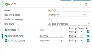
I2C:  SCL is master but your pinumx use RX enable for I2C SCL.  Do you have any comments about the I2C SCK is output signal but you pinmux set are RX ?

GPIO: your pinmux set all gpio is RX enable, but I don't think the Jacinto 7 EVM use all GPIO as input in schematic. 

OSPI: your pinmux set all D0~D7 are RX enable, but those data signal are bi-direction . Do you have any comments about the bi-direction data signal but pinux set are RX. 

BTW: where are we can set the pad from push-pull to open drain in pinmux tools. 

Thanks

Yutai

  • Hi Yutai,

    https://dev.ti.com/sysconfig/?fromPinmux=true#/start

    Have you tried the above tool?

    At the pad level RX is set. Is that causing a problem?

    Pull Up/Down menu has No Pull is that what you are asking for in the last question?

    - Keerthy

  • Hi Keerthy

    Yes, I use the sysconfig tools. 

    I want to know why those signal is output but the pinmux /sysconfig tools set as output (RX enable) 

    3.4.3. Pin Mux Tools — Processor SDK Linux for J721e Documentation

    RX Enable / Input Enable

    Most devices, K2G excluded, support the ability to disable the input buffer on a pin. When the RX buffer is disabled the pin can still be used as an output for clocks and GPIO but it cannot be used as an input for any function.

    Many peripherals require the input buffer to be enabled even if it is an output.

    Examples are I2C clock, MDIO clock, SPI chip select, MMC/SD clock & cmd lines, etc.

    For the most part, the PinMux Tool will not let you disable the input buffer on pins that require it.

    My last question is about buffer type. Push-Pull / Open drain ...... setting, It is not the internal resistor Pull up / Pull down / No Pull setting.  

    Thanks

    Yutai

  • I want to know why those signal is output but the pinmux /sysconfig tools set as output (RX enable) 

    It is configurable. You can untick that blue tick on the RX column.


    My last question is about buffer type. Push-Pull / Open drain ...... setting, It is not the internal resistor Pull up / Pull down / No Pull setting.  

    No. Also which bit corresponds to open drain Vs push-pull? If there is no bit then they will not model that correct?

    - Keerthy

  • Hi Keerthy

    I find the SDK document show: I2C clock need enabled input buffer. 

    My question is that when we use I2C are Master, so the I2C clock is output, why you/your document suggestion to use RX enable ( enable input buffer)

    3.4.3. Pin Mux Tools — Processor SDK Linux for J721e Documentation

    RX Enable / Input Enable

    Most devices, K2G excluded, support the ability to disable the input buffer on a pin. When the RX buffer is disabled the pin can still be used as an output for clocks and GPIO but it cannot be used as an input for any function.

    Many peripherals require the input buffer to be enabled even if it is an output.

    Examples are I2C clock, MDIO clock, SPI chip select, MMC/SD clock & cmd lines, etc.

    Thanks

    Yutai

  • Are you asking why Master I2C clock is output, but still requires RX enable?  This is because the I2C clock is looped back at the pad (not internally).  So for data to be latched for ACKs, READs, etc - it uses the clock available on the PAD (yes, which also happens to be output from the device).  This way - the architecture is exactly same for master and slave - uses clock at the pad.

  • Hi  Robert 

    Thanks for your comments, Yes, This is my query about I2C clock and it used for looped back as you mention. 

    Thanks

    Yutai