This thread has been locked.

If you have a related question, please click the "Ask a related question" button in the top right corner. The newly created question will be automatically linked to this question.

TSIF Clock Load Termination Impedance

Other Parts Discussed in Thread: SN74CBT16214

Hello,

We have (mostly) ported the old TSIF driver from  LSP 1.30 to Linux kernel 2.6.32 to work with our dm6467 EVM (from spectrum digital).  However we are having some strange issues with the clock.  Let me describe our current setup:

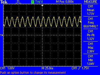
We have an ML507 (Xilinx Virtex-5 FPGA dev board) driving TSIF signals (control and data) to the DC_P2 socket on the dm6467 EVM.  The TSIF clock line is being driven at 20MHz.  The two boards are connected via discrete 30 AWG wires.  On the DaVinci side these wires are soldered to a removable header, and are wire-wrapped to 0.1" pins on the FPGA side.

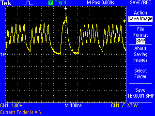
We receive data perfectly...as long as an oscilloscope probe is attached to the clock line, or some other capacitance-adding device is loaded (for kicks, we stuck a wire-wrap tool on the .1" FPGA header pin, and that was enough to get it to work).

So my question is, (if this is in fact an impedance matching issue) does anyone know what is the input impedance is on the PTSI_CLK pin?  This pin runs through a 22 ohm resistor and then into a mux/demux (SN74CBT16214) which then terminates into pin AC19 on the DaVinci.

Could there be another cause for this odd behavior?  Noise from the switching power supplies perhaps?


Thank you

  • Hi,

    Can u provide oscope captures of the passing and failing case, with the probes placed on the clock and data lines as near to the DM6467 as possible.

    Regards, Srirami.

  • Here are the waveforms from our tests when we used a 60MHz clock, these failed.

    The waveforms look pretty much identical when run at 20MHz (just the time division is different and the clock line is able to produce a full swing from 0v-3.3v).  Other than that, the actual shape is exactly the same.

    I cannot provide you with the slower waveforms when the tests failed because probing the line causes the test to pass at 20MHz.


    Thanks


    Clock:


    Data pin [0] (LSB):

  • Thanks for the waveforms. These waveforms are not very useful at 60MHz since they only have around a 1.3V swing! It would probably be more useful to see the passing waveforms at 20MHz, with the clock and date both captured on the same screen (so we can see how marginal the setup/hold times are.

    Regards, Srirami.

  • Hi srirami,

    Thank you for following up with me.  We were able to figure out the problem.  We were using high-speed high-current FETs on the FPGA to drive the signal.  When we used slow, lower current FETs, we were able to drive the signal properly.  At least at 20MHz.  We are still experimenting with 60MHz.


    Thanks again!