This thread has been locked.

If you have a related question, please click the "Ask a related question" button in the top right corner. The newly created question will be automatically linked to this question.

TMDSIDK574: How to configure PWMSS1 Timebase for AM5749

Part Number: TMDSIDK574

Hi Everyone,

I want to configure PWMSS1 based on time for AM5749 processor.  For that i have referred AM5749 Technical Reference Manual section 30. I want to configure gpio4_0 as an epwm. So for that with some reference i have configure as per the attached file(pwm.c and pwm.h)


/**
 * main.c
 */

#include "pwm.h"


CSL_EpwmAqActionCfg_t aqctrla = {AQ_NO_ACTION, AQ_CLEAR, AQ_TOGGLE, AQ_NO_ACTION, AQ_NO_ACTION, AQ_NO_ACTION};

/* Function to setup PWM module one-time configurations */
static void BoardDiag_pwmInit(uint32_t pwmssBaseAddr)
{
    /*Time base clock configuring using prescaler*/
    CSL_epwmTbTimebaseClkCfg(pwmssBaseAddr, TBCLK_FREQ, MODULE_CLK);

    /*Clearing phase and direction set to count up*/
    CSL_epwmTbSyncEnable(pwmssBaseAddr, CLEAR_PHASE_REG, TB_COUNT_UP);

    /*Disabling the Sync*/
    CSL_epwmTbSyncDisable(pwmssBaseAddr);

    /*Configuring the EPWM_AQCTLA register*/
    CSL_epwmAqActionOnOutputCfg(pwmssBaseAddr, CSL_EPWM_OUTPUT_CH_A, &aqctrla);
}

/* Function to configure PWM pulse generation */
static void BoardDiag_pwmConfig(uint32_t pwmssBaseAddr, float dutyCycle)
{
    float period = TBCLK_FREQ/PWM_FREQ;

     /* This is the compare count value to be configured to
      * generate the requested dutyCycle.
      */
     uint32_t cmpCntVal = (period - (uint32_t)(period * (dutyCycle/100)));

     /* PWM pulse frequency configuration */
     CSL_epwmTbPwmFreqCfg(pwmssBaseAddr, TBCLK_FREQ, PWM_FREQ, TB_COUNT_UP,
                          TB_IMMEDIATE);

     /* Configuring EPWM_CMPCTL register */
     CSL_epwmCounterComparatorCfg(pwmssBaseAddr, CSL_EPWM_CC_CMP_A,
                                  cmpCntVal, CC_SHADOW,
                                  CC_CTR_ZERO, OVER_WRITE_SHADOW_DISABLED);

     /* Resetting the counter */
     CSL_epwmTbWriteTbCount(pwmssBaseAddr, RESET_TB_COUNT_VALUE);
}

/* Enables clock for PWM module */
static void BoardDiag_pwmClockConfig(void)
{
#if defined(evmAM335x)
    /* Enable PRCM for PWMSS0 */
    HW_WR_REG32((SOC_CM_PER_REGS + CM_PER_EPWMSS0_CLKCTRL), 0x02);

    /* Enable the PWM clock using the PMWSS0 CLKCONFIG Register*/
    HW_WR_REG32((PWM_BASE_ADDRESS + PWMSS_CLKCONFIG), 0x100);

    /* Time base clock for PWMSS1 module */
    HW_WR_REG32((SOC_CONTROL_REGS + CONTROL_PWMSS_CTRL), 0x1);
#elif defined(evmAM572x)
    /* Enable PRCM for PWMSS2 */
    HW_WR_REG32(SOC_L4PER_CM_CORE_BASE + CM_L4PER2_PWMSS2_CLKCTRL, 0x2);
    while ((HW_RD_REG32(SOC_L4PER_CM_CORE_BASE +
                        CM_L4PER2_PWMSS2_CLKCTRL) & (0x00030000)) != 0x0);
    /* Time base clock for PWMSS2 module */
    HW_WR_FIELD32(SOC_CTRL_MODULE_CORE_CORE_REGISTERS_BASE +
                  CTRL_CORE_CONTROL_IO_2,
                  CTRL_CORE_CONTROL_IO_2_PWMSS2_TBCLKEN, 1);
#elif defined(evmK2G)
    /* Time base clock enable for EHRPWM_3 module */
    HW_WR_REG32((CSL_BOOT_CFG_REGS + BOOTCFG_EPWM_CTL_REG_OFFSET), 0x08);
#elif defined(idkAM437x)
    /* Enabling the pwm clock for the PWMSS2 module */
    HW_WR_REG32(PWM_BASE_ADDRESS + PWMSS_CLKCONFIG, 0x100);

    /*Enabling the Time-base clock for the PWMMSS2 module */
    HW_WR_REG32(SOC_CONTROL_MODULE_REG + CTRL_PWMSS, 0x4);
#elif defined(custom_board)
    /* Enable PRCM for PWMSS1 */
    HW_WR_REG32(SOC_L4PER_CM_CORE_BASE + CM_L4PER2_PWMSS1_CLKCTRL, 0x2);
    while ((HW_RD_REG32(SOC_L4PER_CM_CORE_BASE +
                        CM_L4PER2_PWMSS1_CLKCTRL) & (0x00030000)) != 0x0);
    /* Time base clock for PWMSS1 module */
    HW_WR_FIELD32(SOC_CTRL_MODULE_CORE_CORE_REGISTERS_BASE +
                  CTRL_CORE_CONTROL_IO_2,
                  CTRL_CORE_CONTROL_IO_2_PWMSS1_TBCLKEN, 1);
#endif

}

/* Configures pinmux for PWM module */
static void BoardDiag_pwmPinmuxConfig(void)
{
    uint32_t regVal;

#if defined(evmAM335x)
    regVal = HW_RD_REG32(SOC_CONTROL_REGS + CONTROL_CONF_SPI0_SCLK);
    regVal = ((regVal & ~0x07) | 0x03);
    HW_WR_REG32(SOC_CONTROL_REGS + CONTROL_CONF_SPI0_SCLK, regVal);
#elif defined(evmAM572x)
//    regVal = HW_RD_REG32(CTRL_CORE_PAD_GPIO6_10_ADDR);
    regVal = HW_RD_REG32(0x374U);
    regVal = ((regVal & ~0x0F) | 0x0A);
//    HW_WR_REG32(CTRL_CORE_PAD_GPIO6_10_ADDR, regVal);
    HW_WR_REG32(0x374U, regVal);

#elif defined(evmK2G)
    regVal = HW_RD_REG32(CSL_BOOT_CFG_REGS + BOOTCFG_PAD_CONFIG_REG_73_OFFSET);
    regVal = ((regVal & ~0x0F) | 0x04);
    HW_WR_REG32(CSL_BOOT_CFG_REGS + BOOTCFG_PAD_CONFIG_REG_73_OFFSET, regVal);
#elif defined(idkAM437x)
    regVal = HW_RD_REG32(SOC_CONTROL_MODULE_REG + CTRL_CONF_GPMC_AD8);
    regVal = ((regVal & ~0x0F) | 0x04);
    HW_WR_REG32(SOC_CONTROL_MODULE_REG + CTRL_CONF_GPMC_AD8, regVal);
#elif defined(custom_board)
    regVal = HW_RD_REG32(0x364U);
    regVal = ((regVal & ~0x0F) | 0x0A);
    HW_WR_REG32(0x364U, regVal);
#endif

}

/* Function to generate delay */
static void BoardDiag_pwmAppDelay(uint32_t delay)
{
    volatile uint32_t cnt = 0;

    while(cnt < delay)
    {
        asm("");
        cnt++;
    }
}


int main(void)
{
    uint8_t dutyCycle;

    Board_initCfg boardCfg;

#ifdef PDK_RAW_BOOT
    boardCfg = BOARD_INIT_MODULE_CLOCK |
    BOARD_INIT_PINMUX_CONFIG |
    BOARD_INIT_UART_STDIO;
#else
//    boardCfg = BOARD_INIT_UART_STDIO;
    boardCfg = BOARD_INIT_PINMUX_CONFIG | BOARD_INIT_MODULE_CLOCK | BOARD_INIT_UART_STDIO;

#endif

    Board_init(boardCfg);

    UART_printf("\n*********************************************\n");
    UART_printf("*                 PWM Test                  *\n");
    UART_printf("*********************************************\n");


    BoardDiag_pwmClockConfig();
    BoardDiag_pwmPinmuxConfig();
    BoardDiag_pwmInit(0x4843e000U);

    /* Configures PWM for different duty cycles */
    for(dutyCycle = 25; dutyCycle <= 75; dutyCycle += 25)
    {
        UART_printf("\nGenerating %dKHz PWM pulse with %d Duty Cycle\n", PWM_FREQ/1000, dutyCycle);
        BoardDiag_pwmConfig(PWM_BASE_ADDRESS, dutyCycle);
        BoardDiag_pwmAppDelay(DELAY);
    }

    /* Reset the duty cycle to 50% */
    BoardDiag_pwmConfig(PWM_BASE_ADDRESS, 50);

    UART_printf("\nPWM Test Completed!\n");

    /* Restore the default pin mux since the pin mux is changed for PWM */
    boardCfg = BOARD_INIT_PINMUX_CONFIG;
    Board_init(boardCfg);

    return 0;
}
5037.pwm.h

While building the code i was getting error in the file of csl_epwm.h.I have observed that location of csl_epwm.h is at C:\ti\AM5749\pdk_am57xx_1_0_17\packages\ti\csl. and its source file csl_epwm.c location is at C:\ti\AM5749\pdk_am57xx_1_0_17\packages\ti\csl\src\ip\epwm\V0\priv .

At that time i was getting error as an undefined function for all csl function like CSL_epwmTbTimebaseClkCfg

Then i have shifted these files
csl_epwm.c
csl_epwm.h
cslr_epwm.h
hw_pwmss_epwm.h
hw_pwmss_submodule_offsets.h
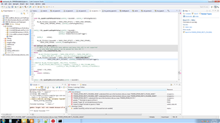
to Project\Include

After that it is giving me error in the HW_WR_FIELD16 as per the attached image

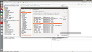
I have following query

1) Does the directory of csl_epwm.h is correct, at C:\ti\AM5749\pdk_am57xx_1_0_17\packages\ti\csl.

2) Whatever method i am following is correct?

3) How to configure ePWM for AM5749 processor?

Thanks & Regards,

Divyesh Patel

  • Hi,

    Does the directory of csl_epwm.h is correct, at C:\ti\AM5749\pdk_am57xx_1_0_17\packages\ti\csl.

    Yes, it is fine.

    Whatever method i am following is correct?

    Instead of directly writing by taking reference, you can try the CSL example first at  ~\pdk_am57xx_1_0_17\packages\ti\csl\example\epwm\epwm_duty_cycle_test_app.

    How to configure ePWM for AM5749 processor?

    you can follow below threads for the reference:

  • Hi Sir,

    Thank you for your feedback.

    Instead of directly writing by taking reference, you can try the CSL example first at  ~\pdk_am57xx_1_0_17\packages\ti\csl\example\epwm\epwm_duty_cycle_test_app.

    Yes, first i have tried with example only.

    In that can i get directly make the ccs project? like project created for GPIO_led_test.

    If yes, i am unable to create project. I have followed the below procedure

    ~\processor_sdk_rtos_am57xx_6_03_00_106$ setupenv.bat

    ~\pdk_am57xx_1_0_17\packages$ pdksetupenv.bat

    ~\pdk_am57xx_1_0_17\packages$gmake LIMIT_SOCS=am574x

    ~\pdk_am57xx_1_0_17\packages\ti\csl$gmake

    If no, how to create project for it?

    I will follow these.

    Thanks & Regards,

    Divyesh Patel

  • Hi Sir,

    Instead of directly writing by taking reference, you can try the CSL example first at  ~\pdk_am57xx_1_0_17\packages\ti\csl\example\epwm\epwm_duty_cycle_test_app.

    As per CSL Introduction, ePWM duty cycle example is limited to the am65xx_evm and j721e_evm.

    Thanks & Regards,

    Divyesh Patel

  • Hi,

    In that can i get directly make the ccs project? like project created for GPIO_led_test.

    It is a makefile based example. You can follow below steps to build it:

    • call pdksetupenv.bat from pdk/package folder.
    • then cd to pdk\packages\ti\csl\example\epwm\epwm_duty_cycle_test_app folder and give gmake BOARD=idkAM574x
    If yes, i am unable to create project.

    you can follow CCS documentation for creating the projects. However, through above mentioned steps you will get binary in pdk/package/ti/binary folder which you can directly load and run through CCS.

    As per CSL Introduction, ePWM duty cycle example is limited to the am65xx_evm and j721e_evm.

    Yeah, it is limited to those, but as mentioned in other thread, you can get the code reference as similar epwm IP is being used.

  • Yeah, it is limited to those, but as mentioned in other thread, you can get the code reference as similar epwm IP is being used.

    Yes, I am trying that only.

    I have linked all files. But i was getting error for the  Board_init(boardCfg); bcz it was unable to link with idkAM574x.c

    Then in the same file of  Board_init(boardCfg) function, i gave the path of idkAM574x.c so it started it giving me following error

    unknown type name 'CSL_watchdogocp2Regs'
    unknown type name 'CSL_control_coreRegs'
    request for member 'WWPS' in something not a structure or union
    request for member 'WWPS' in something not a structure or union
    request for member 'WSPR' in something not a structure or union
    request for member 'WSPR' in something not a structure or union
    request for member 'WDST' in something not a structure or union
    request for member 'MMR_LOCK_5' in something not a structure or union
    request for member 'MMR_LOCK_4' in something not a structure or union
    request for member 'MMR_LOCK_3' in something not a structure or union
    request for member 'MMR_LOCK_2' in something not a structure or union
    request for member 'MMR_LOCK_1' in something not a structure or union
    recipe for target 'main.o' failed
    gmake: Target 'all' not remade because of errors.
    gmake: *** [main.o] Error 1
    expected expression before ')' token
    expected expression before ')' token
    'CSL_watchdogocp2Regs' undeclared (first use in this function); did you mean 'watchdogRegs'?
    'CSL_WATCHDOGOCP2_WWPS_W_PEND_WSPR_SHIFT' undeclared (first use in this function); did you mean 'CSL_WATCHDOGOCP2_WWPS_W_PEND_WSPR_MASK'?
    'CSL_WATCHDOGOCP2_WWPS_W_PEND_WSPR_RESETVAL' undeclared (first use in this function); did you mean 'CSL_WATCHDOGOCP2_WDST_RESETVAL'?
    'CSL_WATCHDOGOCP2_WWPS_W_PEND_WSPR_MASK' undeclared (first use in this function); did you mean 'CSL_WATCHDOGOCP2_WWPS_W_PEND_WSPR_RESETVAL'?
    'CSL_WATCHDOGOCP2_WSPR_WSPR_VALUE_SHIFT' undeclared (first use in this function); did you mean 'CSL_WATCHDOGOCP2_WSPR_WSPR_VALUE_MASK'?
    'CSL_WATCHDOGOCP2_WSPR_WSPR_VALUE_MASK' undeclared (first use in this function); did you mean 'CSL_WATCHDOGOCP2_WDST_RESETDONE_MASK'?
    'CSL_WATCHDOGOCP2_WDST_RESETVAL' undeclared (first use in this function)
    'CSL_WATCHDOGOCP2_WDST_RESETDONE_SHIFT' undeclared (first use in this function); did you mean 'CSL_WATCHDOGOCP2_WDST_RESETDONE_MASK'?
    'CSL_WATCHDOGOCP2_WDST_RESETDONE_MASK' undeclared (first use in this function); did you mean 'CSL_WATCHDOGOCP2_WDST_RESETVAL'?
    'CSL_control_coreRegs' undeclared (first use in this function); did you mean 'ctrlCoreReg'?

    Thanks & Regards,

    Divyesh Patel

  • Hi,

    Can you mention the steps what you are following?

  • Hi

    Can you mention the steps what you are following?

    That is as follow

    • SOC Selection

    Variant AM574x - Cortex A15
    IDK_AM574x[Cortex A]
    connection - Texas Instruments XDS100v2 USB Debug
    Compiler version GNU v7.2.1(Linaro)

    • GNU Compiler Directories


    ${PROJECT_ROOT}
    C:\ti\AM5749\pdk_am57xx_1_0_17\packages\ti\board\src\idkAM574x\include
    C:\ti\AM5749\pdk_am57xx_1_0_17\packages\ti\csl\soc\am574x\src
    C:\ti\xdctools_3_50_07_20_core\packages
    C:\Users\admin\workspace_v9\ePWM\Include
    C:\ti\AM5749\pdk_am57xx_1_0_17\packages
    C:\ti\AM5749\pdk_am57xx_1_0_17
    C:\ti\AM5749\pdk_am57xx_1_0_17\packages\ti\csl\example\epwm
    ${CG_TOOL_INCLUDE_PATH}

    /*
     * Copyright (C) 2017 Texas Instruments Incorporated - http://www.ti.com/
     *
     * Redistribution and use in source and binary forms, with or without
     * modification, are permitted provided that the following conditions
     * are met:
     *
     * Redistributions of source code must retain the above copyright
     * notice, this list of conditions and the following disclaimer.
     *
     * Redistributions in binary form must reproduce the above copyright
     * notice, this list of conditions and the following disclaimer in the
     * documentation and/or other materials provided with the
     * distribution.
     *
     * Neither the name of Texas Instruments Incorporated nor the names of
     * its contributors may be used to endorse or promote products derived
     * from this software without specific prior written permission.
     *
     * THIS SOFTWARE IS PROVIDED BY THE COPYRIGHT HOLDERS AND CONTRIBUTORS
     * "AS IS" AND ANY EXPRESS OR IMPLIED WARRANTIES, INCLUDING, BUT NOT
     * LIMITED TO, THE IMPLIED WARRANTIES OF MERCHANTABILITY AND FITNESS FOR
     * A PARTICULAR PURPOSE ARE DISCLAIMED. IN NO EVENT SHALL THE COPYRIGHT
     * OWNER OR CONTRIBUTORS BE LIABLE FOR ANY DIRECT, INDIRECT, INCIDENTAL,
     * SPECIAL, EXEMPLARY, OR CONSEQUENTIAL DAMAGES (INCLUDING, BUT NOT
     * LIMITED TO, PROCUREMENT OF SUBSTITUTE GOODS OR SERVICES; LOSS OF USE,
     * DATA, OR PROFITS; OR BUSINESS INTERRUPTION) HOWEVER CAUSED AND ON ANY
     * THEORY OF LIABILITY, WHETHER IN CONTRACT, STRICT LIABILITY, OR TORT
     * (INCLUDING NEGLIGENCE OR OTHERWISE) ARISING IN ANY WAY OUT OF THE USE
     * OF THIS SOFTWARE, EVEN IF ADVISED OF THE POSSIBILITY OF SUCH DAMAGE.
     *
     */
    
     /**
     *  \file   pwm_test.c
     *
     *  \brief  PWM diagnostic test file
     *
     *  Targeted Functionality: Validating the CSL functional layer APIs for
     *  PWM module
     *
     *  Operation: This tests demonstrate the usage of PWM CSL FL APIs by
     *  configuring the PWM module to generate a pulse of 1KHz with different
     *  duty cycle - 25, 50 and 75%.
     *
     *  Supported SoCs: K2G, AM572x, AM437x & AM335x
     *
     *  Supported Platforms: evmK2G, evmAM572x, idkAM437x & evmAM335x
     *
     *  Note: Manual verification is needed to confirm the PWM pulse generation.
     *  Details of PWM pin used on each platform is given below
     *  evmK2G     - J12 pin 33
     *  evmAM572x  - P17 pin 5
     *  idkAM437x  - J16 pin 14
     *  evmAM335x  - J5 pin 13
     *
     */
    
    #include "pwm.h"
    
    CSL_EpwmAqActionCfg_t aqctrla = {AQ_NO_ACTION, AQ_CLEAR, AQ_TOGGLE, AQ_NO_ACTION, AQ_NO_ACTION, AQ_NO_ACTION};
    
    /* Function to setup PWM module one-time configurations */
    static void BoardDiag_pwmInit(uint32_t pwmssBaseAddr)
    {
        /*Time base clock configuring using prescaler*/
        CSL_epwmTbTimebaseClkCfg(pwmssBaseAddr, TBCLK_FREQ, MODULE_CLK);
    
        /*Clearing phase and direction set to count up*/
        CSL_epwmTbSyncEnable(pwmssBaseAddr, CLEAR_PHASE_REG, TB_COUNT_UP);
    
        /*Disabling the Sync*/
        CSL_epwmTbSyncDisable(pwmssBaseAddr);
    
        /*Configuring the EPWM_AQCTLA register*/
        CSL_epwmAqActionOnOutputCfg(pwmssBaseAddr, CSL_EPWM_OUTPUT_CH_A, &aqctrla);
    }
    
    /* Function to configure PWM pulse generation */
    static void BoardDiag_pwmConfig(uint32_t pwmssBaseAddr, float dutyCycle)
    {
        float period = TBCLK_FREQ/PWM_FREQ;
    
        /* This is the compare count value to be configured to
         * generate the requested dutyCycle.
         */
        uint32_t cmpCntVal = (period - (uint32_t)(period * (dutyCycle/100)));
    
        /* PWM pulse frequency configuration */
        CSL_epwmTbPwmFreqCfg(pwmssBaseAddr, TBCLK_FREQ, PWM_FREQ, TB_COUNT_UP,
                             TB_IMMEDIATE);
    
        /* Configuring EPWM_CMPCTL register */
        CSL_epwmCounterComparatorCfg(pwmssBaseAddr, CSL_EPWM_CC_CMP_A,
                                     cmpCntVal, CC_SHADOW,
                                     CC_CTR_ZERO, OVER_WRITE_SHADOW_DISABLED);
    
        /* Resetting the counter */
        CSL_epwmTbWriteTbCount(pwmssBaseAddr, RESET_TB_COUNT_VALUE);
    }
    
    /* Enables clock for PWM module */
    static void BoardDiag_pwmClockConfig(void)
    {
    #if defined(evmAM335x)
        /* Enable PRCM for PWMSS0 */
        HW_WR_REG32((SOC_CM_PER_REGS + CM_PER_EPWMSS0_CLKCTRL), 0x02);
    
        /* Enable the PWM clock using the PMWSS0 CLKCONFIG Register*/
        HW_WR_REG32((PWM_BASE_ADDRESS + PWMSS_CLKCONFIG), 0x100);
    
        /* Time base clock for PWMSS1 module */
        HW_WR_REG32((SOC_CONTROL_REGS + CONTROL_PWMSS_CTRL), 0x1);
    #elif defined(evmAM572x)
        /* Enable PRCM for PWMSS2 */
        HW_WR_REG32(SOC_L4PER_CM_CORE_BASE + CM_L4PER2_PWMSS2_CLKCTRL, 0x2);
        while ((HW_RD_REG32(SOC_L4PER_CM_CORE_BASE +
                            CM_L4PER2_PWMSS2_CLKCTRL) & (0x00030000)) != 0x0);
        /* Time base clock for PWMSS2 module */
        HW_WR_FIELD32(SOC_CTRL_MODULE_CORE_CORE_REGISTERS_BASE +
                      CTRL_CORE_CONTROL_IO_2,
                      CTRL_CORE_CONTROL_IO_2_PWMSS2_TBCLKEN, 1);
    #elif defined(evmK2G)
        /* Time base clock enable for EHRPWM_3 module */
        HW_WR_REG32((CSL_BOOT_CFG_REGS + BOOTCFG_EPWM_CTL_REG_OFFSET), 0x08);
    #elif defined(idkAM437x)
        /* Enabling the pwm clock for the PWMSS2 module */
        HW_WR_REG32(PWM_BASE_ADDRESS + PWMSS_CLKCONFIG, 0x100);
    
        /*Enabling the Time-base clock for the PWMMSS2 module */
        HW_WR_REG32(SOC_CONTROL_MODULE_REG + CTRL_PWMSS, 0x4);
    #endif
    }
    
    /* Configures pinmux for PWM module */
    static void BoardDiag_pwmPinmuxConfig(void)
    {
        uint32_t regVal;
    
    #if defined(evmAM335x)
        regVal = HW_RD_REG32(SOC_CONTROL_REGS + CONTROL_CONF_SPI0_SCLK);
        regVal = ((regVal & ~0x07) | 0x03);
        HW_WR_REG32(SOC_CONTROL_REGS + CONTROL_CONF_SPI0_SCLK, regVal);
    #elif defined(evmAM572x)
        regVal = HW_RD_REG32(CTRL_CORE_PAD_GPIO6_10_ADDR);
        regVal = ((regVal & ~0x0F) | 0x0A);
        HW_WR_REG32(CTRL_CORE_PAD_GPIO6_10_ADDR, regVal);
    #elif defined(evmK2G)
        regVal = HW_RD_REG32(CSL_BOOT_CFG_REGS + BOOTCFG_PAD_CONFIG_REG_73_OFFSET);
        regVal = ((regVal & ~0x0F) | 0x04);
        HW_WR_REG32(CSL_BOOT_CFG_REGS + BOOTCFG_PAD_CONFIG_REG_73_OFFSET, regVal);
    #elif defined(idkAM437x)
        regVal = HW_RD_REG32(SOC_CONTROL_MODULE_REG + CTRL_CONF_GPMC_AD8);
        regVal = ((regVal & ~0x0F) | 0x04);
        HW_WR_REG32(SOC_CONTROL_MODULE_REG + CTRL_CONF_GPMC_AD8, regVal);
    #endif
    }
    
    /* Function to generate delay */
    void BoardDiag_pwmAppDelay(uint32_t delay)
    {
        volatile uint32_t cnt = 0;
    
        while(cnt < delay)
        {
            asm("");
            cnt++;
        }
    }
    
    /*
     *  ======== main ========
     */
    int main(void)
    {
        uint8_t dutyCycle;
    
        Board_initCfg boardCfg;
    
    #ifdef PDK_RAW_BOOT
        boardCfg = BOARD_INIT_MODULE_CLOCK |
        BOARD_INIT_PINMUX_CONFIG |
        BOARD_INIT_UART_STDIO;
    #else
        boardCfg = BOARD_INIT_UART_STDIO;
    //    boardCfg = BOARD_INIT_MODULE_CLOCK |
    //      BOARD_INIT_PINMUX_CONFIG |
    //      BOARD_INIT_UART_STDIO;
    #endif
    
        Board_init(boardCfg);
    
    //    UART_printf("\n*********************************************\n");
    //    UART_printf  ("*                 PWM Test                  *\n");
    //    UART_printf  ("*********************************************\n");
    
    //    BoardDiag_pwmClockConfig();
    //    BoardDiag_pwmPinmuxConfig();
    //    BoardDiag_pwmInit(PWM_BASE_ADDRESS);
    //
    //    /* Configures PWM for different duty cycles */
    //    for(dutyCycle = 25; dutyCycle <= 75; dutyCycle += 25)
    //    {
    ////        UART_printf("\nGenerating %dKHz PWM pulse with %d Duty Cycle\n", PWM_FREQ/1000, dutyCycle);
    //        BoardDiag_pwmConfig(PWM_BASE_ADDRESS, dutyCycle);
    //        BoardDiag_pwmAppDelay(DELAY);
    //    }
    //
    //    /* Reset the duty cycle to 50% */
    //    BoardDiag_pwmConfig(PWM_BASE_ADDRESS, 50);
    //
    ////    UART_printf("\nPWM Test Completed!\n");
    //
    //    /* Restore the default pin mux since the pin mux is changed for PWM */
    //    boardCfg = BOARD_INIT_PINMUX_CONFIG;
    ////    Board_init(boardCfg);
    
        return 0;
    }
    

    2768.pwm.h

    Please ignore the PWM configuration function. Right now i am unable to initialize board function "board_init"

    Thanks & Regards,

    Divyesh Patel

  • Hi,

    It is a makefile based example. You can follow below steps to build it:

    • call pdksetupenv.bat from pdk/package folder.
    • then cd to pdk\packages\ti\csl\example\epwm\epwm_duty_cycle_test_app folder and give gmake BOARD=idkAM574x

    As mentioned can you use these steps to build the binary through makefile instead of CCS project.

    >However, errors you are getting is due to CCS project build properties. You can zip and share the project so that i can reproduce the same on  my side.

  • Hi,

    t is a makefile based example. You can follow below steps to build it:

    • call pdksetupenv.bat from pdk/package folder.
    • then cd to pdk\packages\ti\csl\example\epwm\epwm_duty_cycle_test_app folder and give gmake BOARD=idkAM574x

    As mentioned can you use these steps to build the binary through makefile instead of CCS project.

    Yes, i will try it.

    However, errors you are getting is due to CCS project build properties. You can zip and share the project so that i can reproduce the same on  my side.

    PFA zip file.

    PWM.zip

    Thanks & Regards,

    Divyesh Patel

  • Hi,

    PFA zip file.

    There are lots of path mismatch in the project. I guess you are creating project from scratch. My suggestion is to try modifying on top of the  existing project so that path and other basic details are already in place.

    Yes, i will try it.

    This will be a better approach.

  • Hi Sir,

    There are lots of path mismatch in the project. I guess you are creating project from scratch. My suggestion is to try modifying on top of the  existing project so that path and other basic details are already in place.

    Can you please give me the path directory, which i need to include to create custom project from the scratch for the AM5749?

    Just give me path to initiate the board, rest of the things i will do.

    This will be a better approach.

    Yes, i have done. It's working fine and i am getting PWM on the GPIO4_0.

    But, i want to create project from scratch.So please help me out.

    Thanks & Regards,

    Divyesh Patel

  • Hi,

    Yes, i have done. It's working fine and i am getting PWM on the GPIO4_0.

    Good to hear that. Now you can use it to your requirements.

    But, i want to create project from scratch.So please help me out.

    looping the CCS team.

  • But, i want to create project from scratch.So please help me out.

    What is your main purpose for creating a project in CCS? Is it so that you can build the project from the CCS IDE? If so, there are two options - A full CCS project and a Eclipse CDT makefile project. The former is a project managed by the build system. This allows you to completely configure and build your project using the CCS IDE GUI. This is the most common type of project used with the CCS IDE. The latter is simply a project "wrapper" around an existing makefile. The wrapper project allows you to build the makefile from the CCS IDE GUI, but otherwise any other configuration for the project would require you to manually modify the makefile yourself. This type of project is only helpful if you only want to build inside CCS, not modify. With this latter option, you can take the existing makefile from the SDK and build it from the CCS IDE. If you want the former, then you will need to create it from scratch as you are trying now. This requires a lot of expertise of the existing makefile project and SDK. The SDK people typically do not recommend trying to create a fill CCS project from scratch. If you just want to build from the IDE, you may want to explore the CDT makefile project option.

    help.eclipse.org/.../index.jsp

    Thanks

    ki

  • Hi Sir,

    Thank you so much for your response.

    help.eclipse.org/.../index.jsp

    Yes, i have followed. I can create custom project and also create makefile project. That is not my problem.

    My problem is,

    • Using the source file of AM574x, i am unable to build the project.I am getting error to initialize the board.
    • If i will use any example project of idkAM574x board and modify it, then i can able to get what i want like checking PWM,i2C,SPI or GPIO.
    • But, when i will try to create my own project without using any example then i am unable to link all supported source and header file to initialize the board as i said before.
    Right now i am unable to initialize board function "board_init"

    So my concern is not about to know the method of creating custom project in CCS. I know it.

    "But,it is how to add and which source or header file i need to add to create my own project for the board of idkAM74x"

    Hope you understand my query.

    Thanks & Regards,

    Divyesh Patel

  • I will need to bring this thread to the attention of the device experts. They will be able to assist you further. Sorry for the delay.

    ki

  • Hi sir,

    I will need to bring this thread to the attention of the device experts. They will be able to assist you further. Sorry for the delay.

    NP, i am waiting for the response.

    Thanks & Regards,

    Divyesh Patel

  • Hi,

    There are quite a few files that you need to link internally and externally. Also, you need to mentioned compiler/ linkers, different flags used while compiling/linking. Therefore, as mentioned earlier it is not recommended to write from scratch. 

    But if you want to do that, you can always check any project configuration file. For example, you can go through pdk_am57xx_1_0_17\packages\ti\drv\usb\example\bios\am57xx\USB_DevMsc_idkAM574x_armExampleProject.txt. This file is responsible for creating USB_DEVMSC example for idkAM574.

  • Hi Sir,

    But if you want to do that, you can always check any project configuration file. For example, you can go through pdk_am57xx_1_0_17\packages\ti\drv\usb\example\bios\am57xx\USB_DevMsc_idkAM574x_armExampleProject.txt. This file is responsible for creating USB_DEVMSC example for idkAM574.

    Thank you sir, i was looking for this only.

    One more question is, can i use examples(e.g. USB_DevMSC_idkAM574x_armExampleProject) configuration directly to my custom project?

    If yes,

    How to do it?

    Thanks & Regards,

    Divyesh Patel

  • Hi,

    If you see the project properties in CCS you can see options to modify linkers/compilers settings. you have to do that manually. Thats why, we don't recommend to write from scratch. You can always modify on top of any available example projects which is similar to your required application.

  • Hi Sir,

    If you see the project properties in CCS you can see options to modify linkers/compilers settings. you have to do that manually.

    Are you talking about GNU Compiler & Linker?

  • Are you talking about GNU Compiler & Linker?

    Yes. These are the places where you can introduce your linker and compiler flags. 

    Also, i would suggest to go through each tab under project settings and compare it with the pdk example CCS project settings.

  • Hi Sir,

    Yes. These are the places where you can introduce your linker and compiler flags. 

    Yes Sir,

    With the reference of GPIO LED example, i have given all the required path as follows in the GNU Compiler Directories

    ${PROJECT_ROOT}
    C:\ti\AM5749\pdk_am57xx_1_0_17\packages\ti\board\src\idkAM574x\include
    C:\ti\AM5749\pdk_am57xx_1_0_17\packages\ti\csl\soc\am574x\src
    C:\ti\xdctools_3_50_07_20_core\packages
    C:\Users\admin\workspace_v9\ePWM\Include
    C:\ti\AM5749\pdk_am57xx_1_0_17\packages
    C:\ti\AM5749\pdk_am57xx_1_0_17
    C:\ti\AM5749\pdk_am57xx_1_0_17\packages\ti\csl\example\epwm
    ${CG_TOOL_INCLUDE_PATH}

    And also confirmed the path in the Project-> Includes

    I can see all the included files, but still unable to resolve it.

    Also, i would suggest to go through each tab under project settings and compare it with the pdk example CCS project settings.

    Yes, i have tried. But still something is missing.

    One more doubts i have that when i was following the example of GPIO LED Blink, in the section of GNU Compiler->Directories

    these path were set by flag and in the Resources->Linked Resources

    directory of those flags were defined.

    But the name of the flag used in "GNU Compiler->Directories" is not matching with the "Resources->Linked Resources" .

    So why it is like so?

    or i am linking wrong?

    Thanks & Regards,

    Divyesh Patel

  • Hi,

    Sorry, but this is something that you have to try it yourself as already mentioned it is not recommended.

    But, this is possible. See the attached zipped project where i created GPIO led example from scratch.gpio_ledBlink.zip

  • Hi Sir,

    . See the attached zipped project where i created GPIO led example from scratch.gpio_ledBlink.zip

    Thank you for it.

    Can you please share the steps, how you linked the required files?

    Thanks & Regards,

    Divyesh Patel

  • Hi,

    There are no steps as such, the only thing i did was i compare myProject property and sdkProject property tab by tab and tried to replicate. We can't generalized this more than what is present in CCS documentation.  That's why, we don't recommend to write from scratch.

  • Ok

    Thank you for your support.

    Thanks & Regards,

    Divyesh Patel