This thread has been locked.

If you have a related question, please click the "Ask a related question" button in the top right corner. The newly created question will be automatically linked to this question.

AM5728: QSPI configuration mode transfer example

Part Number: AM5728


Dear Champs,

My customer is using QSPI to connect to FPGA in AM5728 and they need to communicate with FPGA through QSPI using below timing.

As I understand, configuration mode should be used to communicate with FPGA through QSPI, right? 

Is there any example to QSPI transfer in configuration mode?

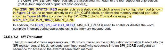
If not, is it OK just to set to '0' in the MMPT_S bit of QSPI_SPI_SWITCH_REG ?

Their SW SDK is Processor Linux SDK v6.3.0 and they will access QSPI in the DSP. So, they need an QSPI configuration mode example working on C66x DSP.

Thanks and Best Regards,

SI.

  • Hi SI,

    I believe there is no such example available on SDK for C6x configuring the QSPI. I will check internally & get back to you.
    I am not too hopeful about this.

    - Keerthy

  • Hi Keerthy,

    Thanks for this information, but my customer already referred these examples and QSPI was used as memory-mapped mode to communicate with flash memory in these examples.

    I think spi_loopback_example is a example code my customer is looking for, but I'm not sure if it can be used also for QSPI.

    Could you please check if configuration mode should used to communicate with FPGA through QSPI? and how configuration mode should be set for this?

    Thanks and Best Regards,

    SI.

  • Hi,

    Could you please check if configuration mode should used to communicate with FPGA through QSPI?

    What do you mean by "configuration mode" here.

    Also, as mentioned in TRM, "QSPI has a memory mapped register interface, which provides a direct interface for accessing data from external SPI devices".

  • Hi,

    I mean they should use 'configuration port' mentioned in TRM to communicate with FPGA(an external SPI device) as below.(24.5.4.4 QSPI Memory Regions(6014 pages)) or not. If so, how they can use this configuration port to communicate with FPGA?

    Thanks and Best Regards,

    SI.

  • Hi,

    You can refer the csl example at ~\pdk\packages\ti\csl\example\qspi\qspi_test\. In main.c file, you will find APIs like QSPISetMAddrSpace(...) and  QSPIConfMAddrSpace(...) after QSPI_Initialize(...) under main(). These are setting MMPT_S bit in QSPI_SPI_SWITCH_REG register responsible for switching between memory-mapped port and configuration port.

    This example is defined for only 8 devicetype(you will see, once go through example), if your device doesn't fall in any of these please refer the code sequence used here as that is most likely to be similar.

    As sdk examples are supposed to run with onboard devices, we don,t have any example to demonstrates communication with external FPGA. But you can refer erase sequence for configuration port settings.

  • Hi,

    Thanks for this fruitful information, and my customer can use configuration port.

    BTW, do you think above customer's timing can be worked by using memory-mapped port? If so, how they should set for it?

    As you see in above timing, what customer want to do is to read 792 bytes from FPGA through QSPI at one time and I'm not sure if this is possible using configuration port. I found below in the TRM(page 6008th) and it seemed the data was only transferred to QSPI_SPI_DATA_REG[] at each word reading/writing and it is needed to tell the QSPI to continue.

    Due to this operation(data read from QSPI_SPI_DATA_REG and tell the QSPI to continue) for each word, some delays(1.5us) observed between each words and data throughput was lower. So, I think they need to check to use memory-mapped port instead, and please help on this.

    Thanks and Best Regards,

    SI.

  • Hi,

    My question is CS signal will be active during data reading. When My customer run the example of 'C:\ti\pdk_am57xx_1_0_17\packages\ti\csl\example\qspi\qspi_test', they found the CS was swing per each word and wants to maintain CS to active during data reading. Could you please let me know if there is a way to maintain CS signal in active during data reading on memory mapped port?

    Thanks and Best Regards,

    SI.

  • Hi,

    Please ask the customer to go through following sections:

    • As mentioned in section 24.5.4.1.6 "The active state of each chip-select can also be controlled through the CSPi (i = 0 to 3) bits of the QSPI_SPI_DC_REG register."
    • Also you can refer section 24.5.4.1.5 for SPI control State Machine explanation.  This also defines some scenario w.r.t. chip select.

  • Hi Anubhav,

    My intention is not control CS active state but to implement burst mode and send bunch of data bytes(action 5 repeated) after address/dummy bytes as described in TRM as below.

    When my customer captured each signals in the QSPI, they found additional 16 CLK and 8 CLK (Red Box) at each data byte(Blue Box) as below. They want to remove these 'Red Boxes' except 1st one and to know why these red box occurred continuously.

    They modified only few things from basic exampled of pdk , and used linear addressing mode as below.

    Thanks and Best Regards,

    SI.

  • Hi Anubhav,

    Any update on this?

    When I checked below, it seems there is no issue in the SBL and Data can be read continually after dummy data as expected.

    Could you please make clarify the difference between flash read function of SBL and QSPI_basicexample of pdk example?

    https://e2e.ti.com/support/processors-group/processors/f/processors-forum/663039/rtos-am5716-qspi-programming-issue?tisearch=e2e-sitesearch&keymatch=qspi%25252525252520AND%25252525252520memory%25252525252520AND%25252525252520mapped

    Thanks and Best Regards,

    SI.