This thread has been locked.

If you have a related question, please click the "Ask a related question" button in the top right corner. The newly created question will be automatically linked to this question.

TDA4VM: How to use chip select for SPIDEV in device tree

Part Number: TDA4VM

Dear Experts 

As title description. My question is :

Our customize board  have two chip select  pin for spi, but it only appears one chip select entry in linux.

I think it could be device tree entry setting problems.

Parts of setting as below :

1. We use SPI3,  "k3-j721e-main.dtsi"

	main_spi3: spi@2130000 {
		compatible = "ti,am654-mcspi","ti,omap4-mcspi";
		reg = <0x0 0x2130000 0x0 0x400>;
		interrupts = <GIC_SPI 187 IRQ_TYPE_LEVEL_HIGH>;
		clocks = <&k3_clks 269 1>;
		power-domains = <&k3_pds 269 TI_SCI_PD_EXCLUSIVE>;
		#address-cells = <1>;
		#size-cells = <0>;
	};

2. pinmux setting, "k3-j721e-common-proc-board.dts"

	main_spi3_pins_default: main_spi3_pins_default {
		pinctrl-single,pins = <
			J721E_IOPAD(0x144, PIN_OUTPUT, 4) /* (Y25) PRG0_PRU1_GPO17.SPI3_CLK */
			J721E_IOPAD(0x148, PIN_OUTPUT, 4) /* (AA26) PRG0_PRU1_GPO18.SPI3_D0 */
			J721E_IOPAD(0x14c, PIN_INPUT, 4) /* (AA29) PRG0_PRU1_GPO19.SPI3_D1 */
			J721E_IOPAD(0x11c, PIN_OUTPUT, 4) /* (AA24) PRG0_PRU1_GPO7.SPI3_CS0 */
			J721E_IOPAD(0xd4, PIN_OUTPUT, 4) /* (AB26) PRG0_PRU0_GPO9.SPI3_CS1 */
		>;
	};

3. Add a spidev node inside the spi3 node like below: "k3-j721e-common-proc-board.dts"

&main_spi3 {
    pinctrl-names = "default";
    pinctrl-0 = <&main_spi3_pins_default>;
    status="okay";
	/*status = "disabled";*/

    spidev@0 {
       spi-max-frequency = <24000000>;
       reg = <0>;
       compatible = "linux,spidev";
	};

	spidev@1 {
       spi-max-frequency = <24000000>;
       reg = <1>;
       compatible = "linux,spidev";

	};
};

4.  Once I boot Linux one should entries like below:

root@j7-evm:~# ls -l /sys/class/spi*
/sys/class/spi_master:
total 0
lrwxrwxrwx 1 root root 0 Apr 10 00:05 spi0 -> ../../devices/platform/bus@100000/2100000.spi/spi_master/spi0
lrwxrwxrwx 1 root root 0 Apr 10 00:05 spi1 -> ../../devices/platform/bus@100000/2110000.spi/spi_master/spi1
lrwxrwxrwx 1 root root 0 Apr 10 00:05 spi2 -> ../../devices/platform/bus@100000/2120000.spi/spi_master/spi2
lrwxrwxrwx 1 root root 0 Apr 10 00:05 spi3 -> ../../devices/platform/bus@100000/2130000.spi/spi_master/spi3
lrwxrwxrwx 1 root root 0 Apr 10 00:05 spi4 -> ../../devices/platform/bus@100000/2140000.spi/spi_master/spi4
lrwxrwxrwx 1 root root 0 Apr 10 00:05 spi5 -> ../../devices/platform/bus@100000/2150000.spi/spi_master/spi5
lrwxrwxrwx 1 root root 0 Apr 10 00:05 spi6 -> ../../devices/platform/bus@100000/2160000.spi/spi_master/spi6
lrwxrwxrwx 1 root root 0 Apr 10 00:05 spi7 -> ../../devices/platform/bus@100000/2170000.spi/spi_master/spi7
lrwxrwxrwx 1 root root 0 Apr 10 00:05 spi8 -> ../../devices/platform/bus@100000/bus@100000:bus@28380000/47000000.fss/47040000.spi/spi_master/spi8
lrwxrwxrwx 1 root root 0 Apr 10 00:05 spi9 -> ../../devices/platform/bus@100000/bus@100000:bus@28380000/47000000.fss/47050000.spi/spi_master/spi9

/sys/class/spidev:
total 0
lrwxrwxrwx 1 root root 0 Apr 10 00:05 spidev3.0 -> ../../devices/platform/bus@100000/2130000.spi/spi_master/spi3/spi3.0/spidev/spidev3.0
root@j7-evm:~# [   23.125333] Initializing XFRM netlink socket

5. But it only appears one SPI ibterface with chip select = 0

root@j7-evm:~# ls /dev/ | grep spidev
spidev3.0

it should display, isn't it?

spidev 3.0 --> with CS0 (AA24) PRG0_PRU1_GPO7.SPI3_CS0

spidev 3.1--> with CS1 (AB26) PRG0_PRU0_GPO9.SPI3_CS1

Do I miss something?

Many Thanks

Gibbs

  • Gibbs,

    Could you try to add:

    ti,spi-num-cs = <2>;

    In your MCSPI DT Node? Something like below:

    main_spi3: spi@2130000 {
    		compatible = "ti,am654-mcspi","ti,omap4-mcspi";
    		reg = <0x0 0x2130000 0x0 0x400>;
    		interrupts = <GIC_SPI 187 IRQ_TYPE_LEVEL_HIGH>;
    		clocks = <&k3_clks 269 1>;
    		power-domains = <&k3_pds 269 TI_SCI_PD_EXCLUSIVE>;
    		#address-cells = <1>;
    		#size-cells = <0>;
    		ti,spi-num-cs = <2>;
    	};

    By default it is set to 1.

    If this works then please click on verify answer.

    - Keerthy

  • Hi,  Keerthy

    SPI3 device node with CS1 appears.

    spidev 3.0 works fine, but spidev 3.1 doesn't work, because I do not capture any physical signal from spidev3.1

    1. DT Modify as below:

    	main_spi3: spi@2130000 {
    		compatible = "ti,am654-mcspi","ti,omap4-mcspi";
    		reg = <0x0 0x2130000 0x0 0x400>;
    		interrupts = <GIC_SPI 187 IRQ_TYPE_LEVEL_HIGH>;
    		clocks = <&k3_clks 269 1>;
    		power-domains = <&k3_pds 269 TI_SCI_PD_EXCLUSIVE>;
    		ti,spi-num-cs = <2>;
    		#address-cells = <1>;
    		#size-cells = <0>;
    	};

    2. check spidev node, it's fine

    root@j7-evm:~# ls /dev/ | grep spidev
    spidev3.0
    spidev3.1

    3. write data to spi 3.0 and physical signal capture

    root@j7-evm:~# ./spidev_test -v -D /dev/spidev3.0 -p "HELLOWORLD"
    spi mode: 0x0
    bits per word: 8
    max speed: 500000 Hz (500 KHz)
    TX | 48 45 4C 4C 4F 57 4F 52 4C 44 __ __ __ __ __ __ __ __ __ __ __ __ __ __ __ __ __ __ __ __ __ __  |HELLOWORLD|
    RX | 00 00 00 00 00 00 00 00 00 00 __ __ __ __ __ __ __ __ __ __ __ __ __ __ __ __ __ __ __ __ __ __  |..........|

    if I .set  /spidev_test -v -D /dev/spidev3.1 -p "HELLOWORLD", No signal out.

    Do I miss something?

    Many Thanks

    Gibbs

  • add more DT information

    &main_spi3 {
        pinctrl-names = "default";
        pinctrl-0 = <&main_spi3_pins_default>;
        status="okay";
    	/*status = "disabled";*/
    
        spidev@0 {
           spi-max-frequency = <24000000>;
           reg = <0>;
           compatible = "linux,spidev";
    
    	   //smi130_acc@0{
      	 	//		spi-max-frequency = <500000>;					
      		//		compatible = "smi130_acc";
      		//		reg = <0>;
      				/*interrupt-parent = <&msmgpio>;
      				interrupts = <115 0>; 
      				smi130_acc,gpio_irq = <&msmgpio 115 0>;*/			
      		//};
    
      		//smi130_gyro@1{
      		//		spi-max-frequency = <500000>;					
      		//		compatible = "smi130_gyro";
      		//		reg = <1>;
      				/*interrupt-parent = <&msmgpio>;
      				interrupts = <13 0>; 
      				smi130_gyro,gpio_irq = <&msmgpio 13 0>;*/
      		//};
    	};
    
    	spidev@1 {
           spi-max-frequency = <24000000>;
           reg = <1>;
           compatible = "linux,spidev";
    
    	};
    
    };

  • Today update,

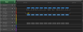
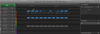
    I wrote a simple SPI read program to test  "/dev/spidev3.1"

    cs1 --> no action

    miso -> have signal, correct 

    mosi -> have signal, corrett

    clk -> yes!

    code as below:

    #include <stdio.h>
    #include <sys/types.h>
    #include <sys/stat.h>
    #include <fcntl.h>
    #include <unistd.h>
    #include <sys/ioctl.h>
    #include <linux/types.h>
    #include <linux/spi/spidev.h>
    #include <stdint.h>
    #include <stdio.h>
    #include <string.h>
    #include <errno.h>
    
    static uint8_t  mode;
    static uint8_t  bits = 8;
    static uint32_t speed = 2*1000;         //32*100*1000; //500000;
    static uint16_t delay = 0;
    
    
    #if 0
    //read operating
    static int transfer_r(int fd,unsigned short addr)
    {
    	int ret;
        unsigned char  cmd[2];
        unsigned char  databuffer[4];
        unsigned char  mydatabuffer[2];
    	struct spi_ioc_transfer	xfer[2];
    	
        
        cmd[0] = addr & 0x00ff; 
        cmd[1] = 0x80 | (addr >> 8); 
        memset(xfer,0,2*sizeof(struct spi_ioc_transfer));
        memset(databuffer,0x00,2);
        xfer[0].tx_buf          = (unsigned long)cmd;
        xfer[0].rx_buf          = NULL;
        xfer[0].len             = 2;
        xfer[0].delay_usecs     = delay;
        xfer[0].bits_per_word   = bits;	
        xfer[0].speed_hz        = speed;


        xfer[1].rx_buf          = (unsigned long)databuffer;
        xfer[1].tx_buf          = NULL;
        xfer[1].len             = 4;
        xfer[1].delay_usecs     = delay;
        xfer[1].bits_per_word   = bits;	
        xfer[1].speed_hz        = speed;


        ret = ioctl(fd, SPI_IOC_MESSAGE(2), &xfer);
    	if (ret == -1 )
    	    printf("can't transfer");
    
    	printf("databuffer[0]=0x%x\n",databuffer[0]);
    	printf("databuffer[1]=0x%x\n",databuffer[1]);
    	printf("databuffer[2]=0x%x\n",databuffer[2]);
    	printf("databuffer[3]=0x%x\n",databuffer[3]);
    
    	return ((databuffer[1] << 8) + databuffer[0]);
    }
    #else
    static int transfer_r(int fd,unsigned short addr)
    {
    	int ret;
        unsigned char  cmd[2];
        unsigned char  databuffer[4];
        unsigned char  mydatabuffer[2];
    	struct spi_ioc_transfer	xfer[2];
        
        cmd[0] = addr & 0x00ff; 
        cmd[1] = 0x80 | (addr >> 8); 
        memset(xfer,0,2*sizeof(struct spi_ioc_transfer));
        memset(databuffer,0x00,2);
        xfer[0].tx_buf          = (unsigned long)cmd;
        xfer[0].rx_buf      = (unsigned long)databuffer;
        xfer[0].len             = 2;
        xfer[0].delay_usecs     = delay;
        xfer[0].bits_per_word   = bits;	
        xfer[0].speed_hz        = speed;
            
    
    	ret = ioctl(fd, SPI_IOC_MESSAGE(1), &xfer);
    	if (ret == -1 )
    	    printf("can't transfer");
    
    	printf("databuffer[0]=0x%x\n",databuffer[0]);
    	printf("databuffer[1]=0x%x\n",databuffer[1]);
    	printf("databuffer[2]=0x%x\n",databuffer[2]);
    	printf("databuffer[3]=0x%x\n",databuffer[3]);
    
    	return ((databuffer[1] << 8) + databuffer[0]);
    	
    }
    #endif
    
    int smi130_read(char *s, unsigned short addr){
    	
    	int len, status, fd;
    	
    	fd = open(s, O_RDWR);
    	
    	if (fd < 0) {
    		perror("open");
    		return 1;
    	}else {
    		printf("Open SPI Port %s\n", s);
    	}
    	
    	status = ioctl(fd, SPI_IOC_WR_MODE, &mode);
    	if (status == -1)
    		printf("can't set spi mode");
    
    	status = ioctl(fd, SPI_IOC_RD_MODE, &mode);
    	if (status == -1)
    		printf("can't get spi mode");
    
    	status = ioctl(fd, SPI_IOC_WR_BITS_PER_WORD, &bits);
    	if (status == -1)
    		printf("can't set bits per word");
    
    	status = ioctl(fd, SPI_IOC_RD_BITS_PER_WORD, &bits);
    	if (status == -1)
    		printf("can't get bits per word");
    
    	status = ioctl(fd, SPI_IOC_WR_MAX_SPEED_HZ, &speed);
    	if (status == -1)
    		printf("can't set max speed hz");
    
    	status = ioctl(fd, SPI_IOC_RD_MAX_SPEED_HZ, &speed);
    	if (status == -1)
    		printf("can't get max speed hz");
    	
    	
    	printf("spi mode: %d\n", mode);
    	printf("bits per word: %d\n", bits);
    	printf("max speed: %d Hz (%d KHz)\n", speed, speed/1000);
    	
    	status = transfer_r(fd, addr);
    	close(fd);
    	
    	return status;
        
    }


    int main(int argc, char **argv)
    {
    	char *name;
    	int ret;
    	//struct spi_ioc_transfer xfer[2];
    	//unsigned char buf[32], *bp;
    	
    	name = argv[1];
    	
    	while(1){
    		ret = smi130_read(name, 0x00);
    		printf("ret = %d\n", ret);
    		usleep(300);
    		
    		ret = smi130_read(name, 0x40);
    		printf("ret = %d\n", ret);
    		usleep(300);
    		
    	    ret = smi130_read(name, 0x60);
    		printf("ret = %d\n", ret);
    		usleep(300);
    	}


    	return 0;
    }

    the problem is why chip select 1 do not work?

    Any Comment?

    Many Thanks

  • Gibbs,

    If I follow it correctly, MISO/MOSI/CLK are all good but CS is not changing.

    Can you double check the CS1 pad configuration is correct as per your custom board?

    Sorry I cannot reproduce as i do not have the board.

    - Keerthy

  • Keerthy ,

    You are right! 

    Our HW make a mistake,  CS1 & MOSI are short.

    The scope shows correct work after HW re-work

    Many Thanks

    Gibbs