This thread has been locked.

If you have a related question, please click the "Ask a related question" button in the top right corner. The newly created question will be automatically linked to this question.

PROCESSOR-SDK-AM64X: DP83822IF

Part Number: PROCESSOR-SDK-AM64X
Other Parts Discussed in Thread: DP83822IF

I'm trying to enable the dp83822if driver under uboot based on SDK8.0 of AM64x.

I want to know how to config the dp83822if as a generic phy driver under uboot?

CONFIG_PHY_TI=y
CONFIG_NETDEVICES=y
CONFIG_DRIVER_TI_CPSW=y

and in phy.c, modify the .uid and .name as below,

.uid = 0x2000a240,
.mask = 0xfffffff0,
.name = "TI DP83822",

Are these configurations enough? 

  • Hi,

    I will need to check with the development team to make sure this is correct. What interface mode will you be using?

    Best Regards,

    Schuyler

  • Will use RGMII, thanks

  • I tried 

    CONFIG_PHYLIB=y

    CONFIG_PHY_TI=y

    CONFIG_DM_ETH=y

    CONFIG_NETDEVICES=y

    CONFIG_RGMII=y

    CONFIG_DRIVER_TI_CPSW=y

    It seems not work, even can not compile success.

    It shows the error below,

    1_2020.01+gitAUTOINC+2781231a33-r36_psdkla_1/git/drivers/net/ti/cpsw.c:21:10: fatal error: asm/arch/cpu.h: No such file or directory
    | 21 | #include <asm/arch/cpu.h>

  • The uboot version i use is 2020.1

  • Hi,

    I consolidated a similar e2e thread that you are asking to this thread.  Which u-boot config file you using to configure the A53 build?

    The variable CONFIG_DRIVER_TI_CPSW=y is variable that should not be set, CONFIG_TI_AM65_CPSW_NUSS=y is the correct driver config. The one you have set is for a different device class.

    I would recommend before proceeding with PHY integration to re-configure the A53 build with the default config defined in the TI SDK which is am64x_evm_a53_defconfig.

    Best Regards,

    Schuyler

  • Hi Schuyler,

    Thanks, I used a customized defconfig based on am64x_evm_a53_defconfig.

    I also tried config as below

    CONFIG_PHY_TI=y

    CONFIG_PHY_TI_GENERIC=y

    CONFIG_PHY_FIXED=y

    CONFIG_DM_ETH=y

    CONFIG_NETDEVICES=y

    CONFIG_TI_AM65_CPSW_NUSS=y

    I also modified the phy addr here in dts file, because our PHT ADDR is 0x3,
    &cpsw3g_mdio {
    /*cpsw3g_phy0: ethernet-phy@0 {*/
    cpsw3g_phy0: ethernet-phy@3 {
    /*reg = <0>;*/
    reg = <0x3>;
    };
    };

    The MDIO interface is the same as the AM64x evm board.

    But it still can not work. 

    ethernet@8000000 PHY: 3 not found
    Could not get PHY for ethernet@8000000: addr 3
    phy_connect() failed
    No ethernet found.

  • Sorry, my MDIO pinmux is not correct. Now the phy driver is registered success, and can read the phy id.

    But can not ping now.

  • Hi,

    That was a good debug step, verifying the pin mux.

    The next step is to make sure packets are leaving the interface. The easiest way is to use wireshark to look for the ARP messages that will be sent by your board as part of the ping command. Are you familiar with wireshark?

    Could you please attach the console output when performing the ping command?

    Best Regards,

    Schuyler 

  • Hi Schuyler,

    Yes, I used wireshark  before. This is the console output,

    => ping 192.168.1.120
    link up on port 1, speed 100, full duplex
    Using ethernet@8000000 device

    ARP Retry count exceeded; starting again
    ping failed; host 192.168.1.120 is not alive

    My PC ip is 192.168.1.120, my board ip is 192.168.1.100

    And the wireshark did not show any ARP message

  • I add some debug print

    => ping 192.168.1.120
    --- net_loop Entry
    --- net_loop UDP handler set (0000000000000000)
    --- net_loop ARP handler set (0000000000000000)
    --- net_loop timeout handler cancelled
    link up on port 1, speed 100, full duplex
    --- NetState set to 0
    --- net_loop Init
    Using ethernet@8000000 device
    --- net_loop timeout handler set (000000009ffa5ab0)
    sending ARP for 192.168.1.120
    ARP broadcast 1
    ++++++[am65_cpsw_send], enter
    ARP broadcast 2
    ++++++[am65_cpsw_send], enter
    ARP broadcast 3
    ++++++[am65_cpsw_send], enter
    ARP broadcast 4
    ++++++[am65_cpsw_send], enter

    ARP Retry count exceeded; starting again
    --- NetState set to 3
    --- NetState set to 3
    --- net_loop UDP handler set (0000000000000000)
    --- net_loop ARP handler set (0000000000000000)
    --- net_loop timeout handler cancelled
    --- net_loop Fail!
    --- NetState set to 0
    ping failed; host 192.168.1.120 is not alive

  • Hi,

    The dp83822 is 100M phy, so do we have to modify any CPSW configuration to adapt this?

  • Hi,

    After checking with the development team this should be the only flag necessary, CONFIG_PHY_TI to be set and DT support. Could you please a snippet or picture of the schematic showing the CPSW port and PHY setup.

    Also please attach the portion of the DTS that shows the pin mux for the CPSW port. 

    Since Wireshark is not showing any output please check the pin mux. Since the link is up then perhaps this might be a pin mux issue.

    Best Regards,

    Schuyler

  • Hi Schuyler,

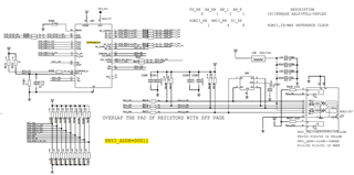
    This is the schematic for the PHY,

    And this is for the CPSW side,

    And my DTS about the ethernet config parts,

    aliases {
    ...
    ethernet0 = &cpsw_port1;
    ethernet1 = &cpsw_port2;
    ...
    };

    cpsw3g: ethernet@8000000 {
    compatible = "ti,am64-cpsw-nuss";
    #address-cells = <2>;
    #size-cells = <2>;
    reg = <0x0 0x8000000 0x0 0x200000>;
    reg-names = "cpsw_nuss";
    ranges = <0x0 0x0 0x0 0x8000000 0x0 0x200000>;
    clocks = <&k3_clks 13 0>;
    assigned-clocks = <&k3_clks 13 1>;
    assigned-clock-parents = <&k3_clks 13 9>;
    clock-names = "fck";
    power-domains = <&k3_pds 13 TI_SCI_PD_EXCLUSIVE>;

    dmas = <&main_pktdma 0xC500 0>,
    <&main_pktdma 0xC501 0>,
    <&main_pktdma 0xC502 0>,
    <&main_pktdma 0xC503 0>,
    <&main_pktdma 0xC504 0>,
    <&main_pktdma 0xC505 0>,
    <&main_pktdma 0xC506 0>,
    <&main_pktdma 0xC507 0>,
    <&main_pktdma 0x4500 0>;
    dma-names = "tx0", "tx1", "tx2", "tx3", "tx4", "tx5", "tx6",
    "tx7", "rx";

    ethernet-ports {
    #address-cells = <1>;
    #size-cells = <0>;

    cpsw_port1: port@1 {
    reg = <1>;
    ti,mac-only;
    label = "port1";
    phys = <&phy_gmii_sel 1>;
    mac-address = [00 00 de ad be ef];
    };

    cpsw_port2: port@2 {
     reg = <2>;
     ti,mac-only;
     label = "port2";
     phys = <&phy_gmii_sel 2>;
    mac-address = [00 01 de ad be ef];
    };
    };

    cpsw3g_mdio: mdio@f00 {
    compatible = "ti,cpsw-mdio","ti,davinci_mdio";
    reg = <0x0 0xf00 0x0 0x100>;
    #address-cells = <1>;
    #size-cells = <0>;
    clocks = <&k3_clks 13 0>;
    clock-names = "fck";
    bus_freq = <1000000>;
    };

    &cpsw3g {
    pinctrl-names = "default";
    pinctrl-0 = <&mdio1_pins_default
    &rgmii1_pins_default>;
    };

    &cpsw_port1 {
    phy-mode = "rgmii-id";
    phy-handle = <&cpsw3g_phy0>;
    };

    &cpsw3g_mdio {
        cpsw3g_phy0: ethernet-phy@3 {
        reg = <0x3>;
        };
    };

    &main_pmx0 {
    mdio1_pins_default: mdio1-pins-default {
    pinctrl-single,pins = <
    AM64X_IOPAD(0x015c, PIN_OUTPUT, 4) /* (Y6) PRG1_MDIO0_MDC.MDIO0_MDC */
    AM64X_IOPAD(0x0158, PIN_INPUT, 4) /* (AA6) PRG1_MDIO0_MDIO.MDIO0_MDIO */
    >;
    };

    rgmii1_pins_default: rgmii1-pins-default {
    pinctrl-single,pins = <
    AM64X_IOPAD(0x0108, PIN_INPUT, 4) /* (W11) PRG1_PRU1_GPO0.RGMII2_RD0 */
    AM64X_IOPAD(0x010c, PIN_INPUT, 4) /* (V11) PRG1_PRU1_GPO1.RGMII2_RD1 */
    AM64X_IOPAD(0x0110, PIN_INPUT, 4) /* (AA12) PRG1_PRU1_GPO2.RGMII2_RD2 */
    AM64X_IOPAD(0x0114, PIN_INPUT, 4) /* (Y12) PRG1_PRU1_GPO3.RGMII2_RD3 */
    AM64X_IOPAD(0x0120, PIN_INPUT, 4) /* (U11) PRG1_PRU1_GPO6.RGMII2_RXC */
    AM64X_IOPAD(0x0118, PIN_INPUT, 4) /* (W12) PRG1_PRU1_GPO4.RGMII2_RX_CTL */
    AM64X_IOPAD(0x0134, PIN_OUTPUT, 4) /* (AA10) PRG1_PRU1_GPO11.RGMII2_TD0 */
    AM64X_IOPAD(0x0138, PIN_OUTPUT, 4) /* (V10) PRG1_PRU1_GPO12.RGMII2_TD1 */
    AM64X_IOPAD(0x013c, PIN_OUTPUT, 4) /* (U10) PRG1_PRU1_GPO13.RGMII2_TD2 */
    AM64X_IOPAD(0x0140, PIN_OUTPUT, 4) /* (AA11) PRG1_PRU1_GPO14.RGMII2_TD3 */
    AM64X_IOPAD(0x0148, PIN_OUTPUT, 4) /* (Y10) PRG1_PRU1_GPO16.RGMII2_TXC */
    AM64X_IOPAD(0x0144, PIN_OUTPUT, 4) /* (Y11) PRG1_PRU1_GPO15.RGMII2_TX_CTL */
    >;
    };

    ...

    };

  • When using the PING cmd, we can not catch any signal on the RGMII data pins, TX CTL and RX CTL. But the RGMII RX CLK and TX CLK both have the 25MHz clk signal.

  • Hi,

    Thank you for the schematic and the dts file. I will review this and respond next week, there is a holiday here in the US on Monday.

    Best Regards,

    Schuyler

  • Hi Schuyler,

    I can ping now.

    Our customized board use RGMII2, and at first I don't know that the RGMII2 must be defined as port2 in DTS. And even I defined it as port2, I changed port2 status="okay", but it still can not use port2. Finally, I hardcode port2 in CPSW driver, and then I can use it successfully.

    So could you help to check that how can it enable the port2 in DTS files?

  • Hi,

    I am glad to hear that you can ping now, that is great progress.

    I will have to check again with the development team. Based on the schematic and just to confirm, you only want to use port2 or RGMII2?

    Would you be able to attach a patch showing the work you did to make port2 work? Also a patch of the DTS change that you created?

    Best Regards,

    Schuyler

  • Hi Schuyler,

    In the DTS, I made below modifications,

    changed the MDIO pinmux to match our board,

    mdio1_pins_default: mdio1-pins-default {
    pinctrl-single,pins = <
    AM64X_IOPAD(0x015c, PIN_OUTPUT, 4) /* (Y6) PRG1_MDIO0_MDC.MDIO0_MDC */
    AM64X_IOPAD(0x0158, PIN_INPUT, 4) /* (AA6) PRG1_MDIO0_MDIO.MDIO0_MDIO */
    >;
    };

    Added cpsw_port2 label information and modified cpsw3g_mdio label information,

     &cpsw_port2 {
    status = "okay";
    phy-mode = "rgmii-id";
    phy-handle = <&cpsw3g_phy3>;
    };

    &cpsw3g_mdio {
    cpsw3g_phy0: ethernet-phy@4 {
    reg = <0x4>;
    };
    cpsw3g_phy3: ethernet-phy@3 {
    reg = <0x3>;
    };
    };

    In the CPSW NUSS driver function am65_cpsw_probe_cpsw, I hardcode the port2 enabled,

    if (!port_id)
    continue;
    + if(port_id == 2)
    + {
    + disabled = false;
    + }

    I'm confused that I have modified cpsw_port2 in DTS with status='okay' , but in the function am65_cpsw_probe_cpsw, still got the cpsw_port2 disabled. So I have to hardcode like above.

  • I wan to use both cpsw_port1 and cpsw_port2. My understanding is that cpsw_port2 is with rgmii2, and it can not be defined to use cpsw_port2 with rgmii1, am I right?

  • Hi,

    First thank you for sharing the code modifications that you performed.

    The TI U-Boot driver only supports 1 port and after checking with the development team only the driver currently only supports port 1. It should support port 2 which it does not. This is a bug that will be noted to be resolved. Your changes that you made will have to work for the time being if you want to use port 2.

    I will make the next comment based on what you indicated on the desire of using both port 1 and port 2. The TI U-Boot driver will only support one port being enabled. The driver does not have the ability to switch between the two ports at run time or by environment variable. If you want to use both ports two different builds will have to be made. This would be after the enabling of port is integrated. 

    Best Regards,

    Schuyler

  • I understand, thank you!