


Part Number: AM5728
Other Parts Discussed in Thread: AM5729, TEST2
Hi,
Board: beaglebone AI,
CPU:AM5729
The customer intends to configure the timer3 interrupt, the interrupt parameters are configured as follows:
Step 1: Register the timer 3 interrupt service function to the vector table by calling the interrupt vector table initialization function in the F:\ti\pdk_am57xx_1_0_17 directory.
void CSL_A15_INIT_copyVectorTable(void)
{
uint32_t vectorBase = 0x40300000U;

uint32_t vectorOffset = (512U * 1024U) - 0x400U;

uint32_t *dest;
uint32_t const *src = (uint32_t const *)vecTbl;
uint32_t count;

if (&__vector_base__)
{
vectorBase = (uint32_t) &__vector_base__;
}
else
{
vectorBase += vectorOffset;
}
dest = (uint32_t *) vectorBase;
CSL_a15SetVectorTable(vectorBase);
for(count = 0; count < (sizeof(vecTbl)/sizeof(vecTbl[0])); count++)
{
dest[count] = src[count];
}
//Intc_IntRegister(4, (IntrFuncPtr)Ethernet_RX_ISR,0);//Register the Gigabit receive interrupt, number 4
//Intc_IntRegister(7, (IntrFuncPtr)Ethernet_TX_ISR,0);//Register the Gigabit transmit interrupt, number 7
//Intc_IntRegister(8, (IntrFuncPtr)MDIO_ISR, 0);//Register the Gigabit MDIO interrupt, number 8
Intc_IntRegister(39,(IntrFuncPtr)Timer3_ISR, 0);//Register the TIMER3 interrupt, number 39
}
Step 2: Configure the interrupt parameters for T3 and the parameters for the A15 interrupt controller GIC respectively
void Init_MPU_INTC(void)
{
Intc_Init();

Init_TIMER3_INTC();
IntMasterIRQEnable(); //Enable the main IRQ interrupt
}

void Init_TIMER3_INTC(void)
{
GICDRegs.Priority[17] = 0x80F0F0F0;//Interrupt 39 priority
Intc_SystemEnable(39); //Interrupt 39 is enabled, corresponding to TIMER3 interrupt
}
void Init_Timer_Interrupt_Parameter(void)
{
GPTIMER3_Regs.IRQEnableSet.bit.OverFlow = 1;//Enable timer overflow interrupt
GPTIMER3_Regs.TCLR.bit.Start_Stop = 1; //Turn on the timer
}
Step 3: Interrupt service function
interrupt void Timer3_ISR(void)
{
Uint32 Status;
Count++;
Test1 = 1;
if(GICDRegs.ISACTIVE[2] == 128)
{
Test2 = ~Test2;
Count1++;
}
GPTIMER3_Regs.IRQSTATUS.bit.OverFlow = 1;
GPTIMER3_Regs.IRQ_EOI.bit.Line_Num = 0;
Status = GICCRegs.IAR;
GICCRegs.EOIR = 71;
//while(GICCRegs.HPPIR != 71);
//Status = GICCRegs.IAR;
Test1 = 0;
}
Issue:
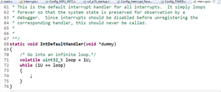
1、The Timer3 interrupt goes into the system default interrupt after each 287 runs, and then running into a dead loop. The customer tries to increase the stack and finds that the larger the stack is set, the more times are entered into Timer3 interrupt. However, no matter how large the stack is set, the default interrupt is eventually entered as shown in the following figure. This should be a problem with the stack. Is there a way to debug?
2、As shown in the figure below, after each interrupt exit, it will quickly re-enter the interrupt.
In the interrupt service function, Test1 and Test2 are two IO ports on the board, and the screenshot shows the measured IO port for Test1.

The partial amplification of a single pulse is as follows:

Of these two adjacent pulses, "GICDRegs.ISACTIVE[2] = = 128" this event occurs in the first pulse. But this event does not occur in the second pulse. A spurious interrupt is mentioned in the GIC document of A15, is this a spurious interrupt?
In the interrupt function, the count value of the variable Count is 287, and Count1 starts adding 1 when GICDRegs.ISAKTIVE[2] = = = 128, so it counts 144, and then the interrupt enters the system default interrupt.
Note:Event GICDRegs.ISACTIVE[2] == 128, because the interrupt priority of T3 is configured with 0x80, which is the value of 128
