This thread has been locked.

If you have a related question, please click the "Ask a related question" button in the top right corner. The newly created question will be automatically linked to this question.

AMIC110: Sneak current between 1.8V to 1.1V

Part Number: AMIC110
Other Parts Discussed in Thread: TPS650250

Hi,

My customer is developing their system with AMIC110 + TPS650250.
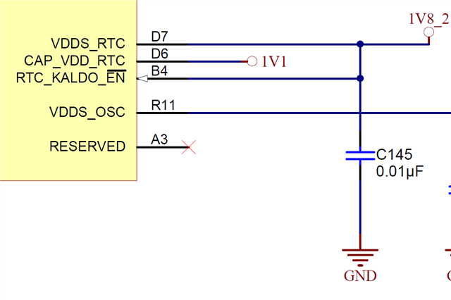
At power-up sequence, they found ~200mV voltage on 1.1V power rail before TPS650250 1.1V output is enabled.
Please see attached waveform and schematics.

AMIC110_1.1V.xlsx

It seems there is sneak current between 1.8V to 1.1V inside AMIC110.
Where should be checked on the board?

Thanks and regards,
Koichiro Tashiro

  • Hi Koichiro,

    Power sequencing is a system level concern where the designer must understand limitations of all on-board and all off-board attached devices.

    Since this is not observed on the AMIC110 ICE but is on the customer board (per the attachment), and not observed on with AMIC110 otherwise, this is likely caused by a configuration of other components on the customer board.

    Is inserting a level shifter an option on the 1.1V rail to block the leakage?

    Regards,

    Colin

  • Hi Colin,

    I am not sure I fully understand your comment below. Could you clarify what does it mean exactly?

    and not observed on with AMIC110 otherwise,


    And could you also explain a bit more about below option?
    I am not familiar to use a level shifter to avoid current leakage. 

    Is inserting a level shifter an option on the 1.1V rail to block the leakage?

    Thanks and regards,
    Koichiro Tashiro

  • Hi Koichiro,

    I am not sure I fully understand your comment below. Could you clarify what does it mean exactly?

    and not observed on with AMIC110 otherwise,

    I am referring to the xlsx attachment, in cell A3:

    "The issue is observed on customer's board, but not on AMIC110 ICE."

    And could you also explain a bit more about below option?
    I am not familiar to use a level shifter to avoid current leakage. 

    Is inserting a level shifter an option on the 1.1V rail to block the leakage?

    The level shifter solution has been implemented by others to help block small amounts of leakage current issues in the past. Most of those issues are in the order of micro-watts while the leakage here is much larger and more like mili-watts.

    Has the customer confirmed the software pullups/pull downs? This seems like something is being contended, where GND is expected but a signal is being pulled high.

    Regards,

    Colin

  • Hi Colin,

    Thanks for your reply.
    Regarding below comment, the signal showing ~200mV is 1.1V power rail itself. So software pulls are not possible.
    And the power rail is connected to AMIC core supply only.

    Has the customer confirmed the software pullups/pull downs? This seems like something is being contended, where GND is expected but a signal is being pulled high.

    Is there any case if some signals are pulled up with 1.8V, it will raise 1.1V power rail GND level?

    Thanks and regards,
    Koichiro Tashiro

  • Hi Koichiro,

    Does the 1.1V power supply power any other component on the board aside from the AMIC110? If so we should confirm that there are no leakage paths in any of those other components.

    And can you please confirm the topology of the CAP_VDD_RTC and RTC_KALDO_EN pins of AMIC110? Does it reflect the topology of the reference board, where 1v1 powers MPU, CORE and CAP_VDD_RTC? And RTC_KALDO_EN is pulled high to 1v8 (which disables the internal LDO)?

    Regards,

    Colin

  • Hi Colin,

    I will send you the details of customer board power rails etc. in offline.
    I was not able to find any suspicious point though.
    Could you check them as well?

    Thanks and regards,
    Koichiro Tashiro

  • Root cause is identified.
    There are three 1.8V rails. They are “+1V8”, “+1V8_LDO1” and “+1V8_LDO2”.
    “+1V8_LDOx” ramp up ~200usec earlier than “+1V8”.
    So below Note G under Figure 6-6 in datasheet is violated.
    VDDS power up later than other 1.8V VDDS_xxx pins.


    Customer temporarily connected all 1.8V rails to “+1V8” then the ~200mV voltage on 1.1V is gone.

    Thanks and regards,
    Koichiro Tashiro