This thread has been locked.

If you have a related question, please click the "Ask a related question" button in the top right corner. The newly created question will be automatically linked to this question.

[FAQ] How do I flash the AM335x SBL and my application into the McSPI flash using the PDK flashing tool?

Other Parts Discussed in Thread: UNIFLASH, AMIC110

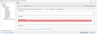
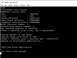
I have an AM335x board with McSPI flash memory. How do I flash my bootloader and application into the McSPI memory using the flashing tool provided in the PDK?

  • There are multiple ways to flash the McSPI memory:

    • Using Uniflash tool, either through UART or JTAG. Please refer to this FAQ.
    • Using the PDK flashing tool through CCS and JTAG. Complete reference can be found here.
    • Both methods require the application binary to be converted to a specific format. Complete reference regarding format conversion can be found here.

    Here we give an example of using the PDK flashing tool to flash the McSPI memory on AMIC110 ICE v2. We will flash both the SBL and an application so that the application will run from the McSPI memory right after a power cycle.

    1. Build an RTOS application. For this example, we chose the PDK example project: GPIO_LedBlink_iceAMIC110_armTestProject.

    • Follow instructions in this FAQ to create PDK example projects. The command to create just this single project is: 
      pdkProjectCreate.bat AM335x iceAMIC110 little gpio test arm
    • Build this project and locate file “app” from the debug folder: C:\ti\pdk_am335x_1_0_17\packages\MyExampleProjects\GPIO_LedBlink_iceAMIC110_armTestProject\Debug.
    • This “app” file is the application image generated during the project build according to the format conversion requirement. Please refer to the Post-build steps in the project settings:

    2. Setup the AMIC110 ICE EVM according to instructions here. Launch a debug session in CCS and connect to the board.

    3. Load the flash writer to the board through CCS: C:\ti\pdk_am335x_1_0_17\packages\ti\starterware\tools\flash_writer\spi_flash_writer_AM335X.out. Then run it in CCS.

    4. When the flash writer runs, CCS console will display the message below and prompts the user to choose an operation:

    [CortxA8] AM335X part detected.
    SF: Got idcode ef 40 17
    Checking if Winbond flash writer can be used..
    SF: Detected W25Q64 with page size 256, total 8388608 bytes
    Flash page size: 256 bytes
    Flash sector size: 4096 bytes
    Starting SPIWriter.
    
     Choose Operation:
     Enter 1 ----> To FLASH an Image
     Enter 2 ----> To ERASE Flash
     Enter 3 ----> To EXIT
    

    • Enter 1 to flash an image.
    • Then enter the full path of the SBL: C:\ti\pdk_am335x_1_0_17\packages\ti\starterware\binary\bootloader\bin\am335x-evm\gcc\bootloader_boot_mcspi_a8host_release_ti.bin.
    • Then enter offset 0x0000.


     Enter 1 ----> To FLASH an Image
     Enter 2 ----> To ERASE Flash
     Enter 3 ----> To EXIT
    1
    Enter the File Name
    C:\ti\pdk_am335x_1_0_17\packages\ti\starterware\binary\bootloader\bin\am335x-evm\gcc\bootloader_boot_mcspi_a8host_release_ti.bin
    Enter the Offset in bytes (in HEX)
    0x00000 
    

    • Let the program run and wait until the flashing finishes.

    5. Repeat step 3 to load and run the flash writer.

    6. Flash the application image:

    • Again choose 1 to flash an image.
    • Then enter the full path of the application image: C:\ti\pdk_am335x_1_0_17\packages\MyExampleProjects\GPIO_LedBlink_iceAMIC110_armTestProject\Debug\app.
    • Enter offset 0x20000.


    Choose Operation:
     Enter 1 ----> To FLASH an Image
     Enter 2 ----> To ERASE Flash
     Enter 3 ----> To EXIT
    1
    Enter the File Name
    C:\ti\pdk_am335x_1_0_17\packages\MyExampleProjects\GPIO_LedBlink_iceAMIC110_armTestProject\Debug\app
    Enter the Offset in bytes (in HEX)
    0x20000
    

    • Let the program run and wait until the flashing finishes.

    7. Stop the CCS debug session. Power cycle the board and LED D17 should blink within a few seconds. If the serial cable is connected, the following message will be displayed in the serial console: