Other Parts Discussed in Thread: TPS65218, TMDSEVM437X
Hi,
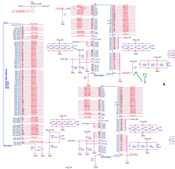
our custom board features AM4376BZDN100, TPS65218D0RSL, single chip 1GB DDR3L single point-to-point connection, 256Mbit QSPI and 8GB eMMC. Board has been in production since 08/2020 and up to now more than 1500 pcs. were produced without any issues related to booting process.
The Linux-4.19.59-215cd90 has been used since the production start. We can also confirm that DDR3 IC populated on the PCB comes now from the new batch (2134 -> Year 2021. Week 34.) and all previous boards have used DDR3 ICs manufactured in 2019.
Now we have been facing booting issues with new boards where DDR3 ICs from new batch are used and boards behave quite strange.
We got 2 boards (SN2798 and SN2819) from our EMS Partner company, have performed some tests and comparison with two boards (SN0011 and SN0008) with older manufacturing date.
Here are some findings:
- There are cases where no response from board on serial debug port UART0 at power up, nothing comes out or black screen.
- There also some cases where the board starts with bootloade, SPL but CRC Checksum Error occurs.
- After the board is powered up and no response on serial debug port (as described under 1) and input power is toggled relatively fast (hundreds of ms), the booting will be executed with no errors and comes up to logging point “….loging:”
See attached picture: SN2819_Scope17_5V_1V8_1V0RTC_DDR_Fast_ON_OFF_Startup.png - Board doesn’t features pressure switch for manual reset but if we apply strong pull down (e.g. 100R) on PMIC_PWR_ON_RST# (Pin 19 of TPS65218D0RSL) the board will go in reset and booting will be again successful.
This was repeated more than 10 times for the same board. - Comparing MCPU_MPU_VDD rails between boards from old and new batch, it has been observed that boards from new batch take 10x more time between power up and vcore scaling event where MPU voltage rail will be switched from 1,1V tio 1,325V.
new batch ~ 3,6 seconds
old batch ~ 0,1 … 0,34 ms
See attached pictures:
SN0011_MPU_VDD.png
SN2798_MPU_VDD.png
SN2819_MPU_VDD.png
Do you have Idea why does it take so long to carry out vcore_scaling at new boards? - Our EMS partner company informed us, that they had tried to replace DDR3 ICs (batch 2134) with ICs from an another batch at 4 boards where the booting issue was occurred.
The outcome was: the booting was executing with no errors and came up to logging point “….loging”: and they also managed to perform flashing of eMMC memory as well.
We have already asked them to check if the vcore_scaling takes so long time, after the DDR3 ICs were swapped. We will let you know as soon as the feedback will be received. - We have also checked power up sequency and it seems fine.
See attached pictures SN2819_Scope01 to 17.
Tomorrow we are going to check I2C communication between Sitara and PMIC and power up sequence at old board in same way as it was done for the new board.
Afterwards DDR signals will be checked.
- Power Sequencing With RTC Feature Enabled, All Dual-Voltage IOs Configured as 3.3 V is used but internal RTC is disabled (XTAL RTC is not running). We are not sure if this can cause any issues.
Could you advise here, what could be additionally checked in order to find out the root of cause ?
If there would be an issue with EMIF settings for DDR3, should it be possible that booting works each time after the second power up or manual reboot?
We had similar issue in development phase, because EMIF was not configured properly at all. But in that case, the DDR3 was crashed somewhere in the middle of Linux booting process and had never reached the end of booting proces (Linux logging point).
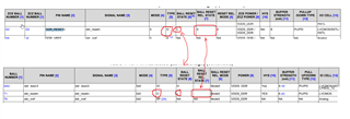
We can also share more details (schematic, Layout, EMIF Config, etc.) over our local TI representative, if needed.
Board_Test_Measurements.zipBr
Josko