A related question is a question created from another question. When the related question is created, it will be automatically linked to the original question.
If you have a related question, please click the "Ask a related question" button in the top right corner. The newly created question will be automatically linked to this question.
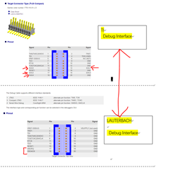
TDA4VM: Is there some document to describe Debug interface ?
The cTI20 provides pins for JTAG, Power/Ground, trace, trigger and control signals. The cTI20's EMU0-4 signals can be used for control, trace, or trigger between a TDA4 and a Lauterbach debug system. The TI reference board/EVM uses a larger MIPI-60 connector which allows for all the trace signals (not just a subset) between the SOC and the debugger. To fully utilize all the signals for a Lauterbach system, multiple debug boxes would be needed. TI recommends the MIPI-60 for external trace as its dimensioning needed for high speed trace sources like the Cortex-A72. A narrow cTI20 interface can be useful for external STM trace+decode but it will have a lot of holes when used for faster sources.
To utilize external pin trace features you would need to have a PowerTRACE box (LA-7694) and preprocessor (LA-7992) in addition to the basic debug box (MIPI-60 recommended). To the cTI20's 5 EMUx signals to export pin trace, you would need to connect the TDA4's TRC_CLK and TRC_DATA0-3 up to the cTI20s EMUx signals then route those signals to the TRACE32 matching TRACE receiver signals. This is what happens for full width system which a MIPI-60 exports using up to 24 TRC_DATAx signals. See the documents and pinouts for these devies: https://www.lauterbach.com/frames.html?pro/pro_dra829v_alt03.php?chip=DRA829V
The cTI20's EMU trace pins are mostly suitable for a lower bandwidth source like a Cortex-M or an STM stream. Lauterbach provides the products like the CombiProbe and MicroTrace https://www.lauterbach.com/frames.html?cortexm_tools.html for this. These boxes 'can' be used with TDA4 (I have used) but they are constrained in usage.
You should check with Lauterbach and see what options they recommend with their tools. They do have TDA4 boards at their HQ and they do fully support debug over JTAG and hardware trace (internal or external). The bottom line is a cTI20 is mostly for JTAG debug and low speed trace commonly found on MCUs, it can be leveraged for some lift on higher end MPUs but the processes is not streamlined for that usage.