This thread has been locked.

If you have a related question, please click the "Ask a related question" button in the top right corner. The newly created question will be automatically linked to this question.

Sensor Controller no I2C traffic

Part Number: CC1352R


I'm trying to setup the sensor controller to read accelerometer (among other things, but just the accelerometer for now) data over I2C. However, I'm not seeing any I2C traffic on the lines when running the Task Testing function of Sensor Controller Studio. I'm looking for data with an oscilloscope.

I've selected I2C Master with the default settings and the Timer 1 Event Trigger as the resources. DIO 28 and 29 are SCL and SDA respectively.

Initialization Code:

evhSetupTimer1Trigger(0, 10, 2);

Event Handler Code:

if (state.i2cStatus == 0x00) {

    i2cDeviceReadReg16LsbFirst(426, 40, output.accelX

}

As a debugging step I added some additional commands to see if that would help resolve the issue. I simply attempted to transmit a single byte in the Initialization Code after the timer setup:

i2cStart();

i2cTx(0x55);

But still no I2C traffic on the pins.

  • Which HW are you running on? Could you confirm that the pull-ups on the I2C lines are mounted? 

  • I have a LaunchXL-CC1352R1. I guess I'm not sure about the pull-ups, I assumed it would work on a development board.

  • The reason I ask is that on some Launchpads these are not mounted since most boosterpacks that uses I2C have pull-ups mounted and you should only have one pull-up, not two in parallel.

    Checked if R2 and R3 is in place, according to the schematic they should be:

    Have you tried this example as is: https://dev.ti.com/tirex/explore/node?node=AJYiAqXR6uR7fnewd7fwFQ__BSEc4rl__LATEST? You don't need to have a board connected to see the I2C communication on the lines. 

  • I do have those pull-ups in place. I used DIO 4 and DIO 5 for testing, they are high until I run the initialization code then they go low and never go high again. Which is odd.

    I am unable to see the example you linked, I simply see a page that says "This resource does not exist. Check your URL or select another resource to view."

  • Sorry, if I paste in a link and continue typing it happens that an extra character end up in the URL which doesn't work too well. Try this: dev.ti.com/.../node

  • Oh I see, the question mark isn't part of the URL. Got it. 

    I loaded up the example. I can see a write on I2C with DIO 4 and DIO5 on the development board. I don't have a sensor, so that's the end of the traffic but it does appear the development board is capable of I2C traffic on those two pins.

    Am I missing something in the sensor controller code to initialize the I2C handle or anything?

  • Have you compared your code to the I2C examples available:

  • It took me a while to locate the examples you showed above but I did get the Light Sensor compiled and running I guess. It would run the initialization code fine but eventually the i2c status would be 0x01. Which I don't really know what that means since the error state documentation isn't clear. I see the same thing when I run my initialization code after i2cStart() is executed. 

    I think as I understand it, i2cStart() transmits a "Setup Read", is that accurate?

  • Running the examples without the correct sensor will sooner or later give an error since the expected response will not be received. But as I understand it you are now able to see something on the I2C bus. 

    From the Sensor Controller Documentation:

    "i2cStart

    Prototype: i2cStart()

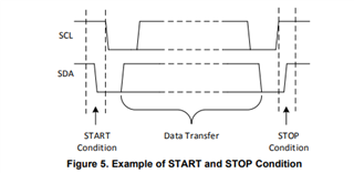
    Clears state.i2cStatus and transmits start condition on the I2C bus."

    From https://www.ti.com/lit/an/slva704/slva704.pdf this should be:

    I2C issues are a bit difficult for us to debug since we don't have the same sensor and therefore are not able to test code. 

    Have you compared the traffic on the I2C bus with what is described in the sensor datasheet? Start to read out a known value, typically the sensor has a register that contains a chip ID or similar. 

  • Thanks for clarifying that. After much more investigation, I've determined the I2C lines were likely always working once I moved to DIO 4 and 5. However, the root of my issue is the Event Handler Code is not being triggered. 

    I call this in the initialization code (Timer 1 because we are using Timer 0 for some ADC sampling):
    evhSetupTimer1Trigger(0, 10, 2);

    But when I run it in the task timing, it never triggers. I make the same call in the Event Handler code to reset the trigger. We use the same call in the ADC sampling task and it seems to work fine. Any ideas?

  • Actually, it started working when running on target and not through Task Testing. For an unknown reason (possibly a bug in Sensor Controller Studio?), the event handler trigger won't trigger on timer 1 in Task Testing, at least in my experience. 

    Things to take away for anyone who finds this thread:

    1. On the LaunchPads DIO 4 and 5 have pull ups on them so use those for I2C.
    2. Be careful with triggers and task testing, they don't always trigger. Run on target with your code if possible.
    3. I2C might error out if it does not receive an ACK during setup, always have a sensor connected when testing.
    4. See last response from TER if confused about what i2cStart() does.

    My working code was essentially what I started with, I guess it was a combination of Task Testing and the wrong I2C pins that were my problem.