This thread has been locked.

If you have a related question, please click the "Ask a related question" button in the top right corner. The newly created question will be automatically linked to this question.

[FAQ] AM62: Power sequence of VDDSHV_MMCx

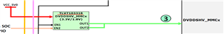
In below Schematic power sequence, why separate VDDSHV_MMCx(VDDSHV5), but other 3.3V VDDSHVn connect to 3V3_SYS, 1.8V VDDSHV connect to 1V8_IO, if VDDSHV_MMCx(VDDSHV5 is 3.3V or 1.8V, can it connect to 3V3_SYS or 1V8_IO?

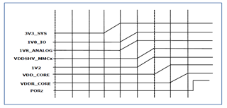
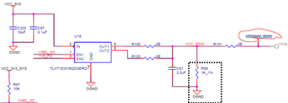
Or the design just leave it configurable for 1.8V or 3.3V by software control VSEL_SD?

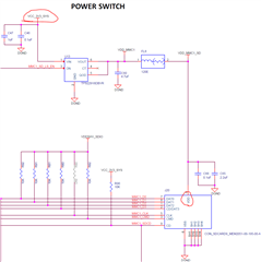
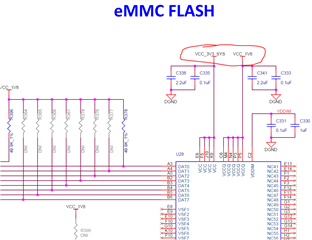
but on the schematic, both SDCARD and eMMC are at fixed voltage

Please help clarify the power supply design purpose for VDDSHV5?.

  • To properly support SD cards, the voltage supply to the card needs to be independently controlled to support 3.3v (for lower speed) and 1.8v (for UHS high speed) operation.  You must also be able to completely cycle power if you perform a cold/warm reset and the ROM attempts to boot from it.

    Regards,

    James

  • James

    Yes, I understand MMC/eMMC IO voltage different at difference mode.

    My questions is:

    #1. the VDDSHV_MMC only connect to AM62x VDDSHV5 pin, not connect to MMC or eMMC card side. how can it meet configurable voltage for card?

    #2. Regarding power sequence, can VDDSHV5(VDDSHV_MMC) or VDDSHV_SDIO can combine with other VDDSHVn together? 

  • The on-board eMMC device is connected to MMC0 and the IOs associated with this port are powered by VDDSHV4. The on-board eMMC device does not need to change voltage dynamically, so VDDSHV4 is connected to a fixed 3.3V or 1.8V supply. Typically on-board eMMC devices are operated at 1.8V.

    The SD Card is connected to MMC1 and the IOs associated with CMD, CLK, and DAT[3:0] are powered by VDDSHV5. These are the IOs that must change their operating voltage dynamically. So the VDDSHV5 power source must default to 3.3V and change to 1.8V when software is ready to change the IO voltage. The IOs associated with SDCD and SDWP are powered by VDDSHV0. These signals only connect to mechanical switches in the SD Card socket and should be pulled high with external pull-up resistors connected to VDDSHV0.  VDDSHV0 can be 3.3V or 1.8V and is not expected to change voltage.

    The SD Card is powered by a fixed 3.3V source and it has a similar internal power supply circuit that changes its IO supply from 3.3V to 1.8V when software sends a command telling the card to change voltage.

    There must be a software switchable 3.3V power source that provides power to the SD Card and the VDDSHV5 power source. The 3.3V power switch is required to cycle power to the SD Card and the VDDSHV5 power rail at the same time anytime the SD Card needs to be reset. Cycling power to the SD Card is the only way it can be reset since there is no reset signal on SD Cards. Without this power switch you would need to cycle power to the entire system to reset the SD Card. The SD Card must be reset anytime it has previously operating at 1.8V and needs to return to 3.3V mode. One good example where you may encounter this problem is when the watchdog timer expires and causes the processor to reset, which will return its VDDSHV5 IO voltage to 3.3V  and the SD Card will still be in 1.8V mode because power didn't cycle. This is a requirement defined in the SD Card specification.

    Regards,
    Paul  

  • Paul,

    understood the different voltage requirement for SD card for different speed.

    From MMC1 circuit, CMD, CLK, and DAT[3:0] are pulled up to VDDSHV5, but card is powered by vcc_3v3_sys, not VDDSHV5. 

  • The SD Card is always powered from a 3.3V source and it has an internal LDO/switch that changes its internal IO power rail. The SD Card IO power rail is not available outside the SD Card, so it can not be used to power the external resistors. Software will change the voltage of VDDSHV5 at the same time it tells the SD Card to change its IO voltage. Therefore, we connect the external resistors to VDDSHV5 since the resistor supply voltage must change at the same time.

    I have inserted a snapshot taken from the SD Card specification that shows and example UHS-I System Block Diagram.

    Hopefully this addresses your question. If not, you need to ask very specific questions.

    Regards,
    Paul