This thread has been locked.

If you have a related question, please click the "Ask a related question" button in the top right corner. The newly created question will be automatically linked to this question.

TDA4VM: TDA4VM:DPI1->ADV7511->hdmi monitor

Part Number: TDA4VM

DPI1->ADV7511->hdmi monitor  

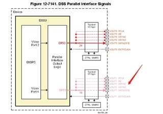
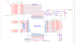
In my TDA4VM board,we use DPI1(Vout1) connect to hdmi monitor as shown above.

we use 16 bit data in vout1.
I made the changes in these files as below. and test with this demo named "gles2-gears", but there is no signal in Vout1 pins.
It will show a picture in screen if it work.

vision_apps/apps/basic_demos/app_tirtos/common/app_cfg_mcu2_0.h
#define ENABLE_DSS_SINGLE
#undef ENABLE_DSS_DUAL
#undef ENABLE_DSS_EDP
#define ENABLE_DSS_HDMI //I difine this macro
#undef ENABLE_DSS_DSI

vision_apps/utils/dss/src/app_dss_defaults.c
int32_t appDssDefaultInit(app_dss_default_prm_t *prm)
{
...
else if(prm->display_type==APP_DSS_DEFAULT_DISPLAY_TYPE_DPI_HDMI)
{
appLogPrintf("DSS: Display type is HDMI !!!\n");
obj->nodeOverlayId = APP_DCTRL_NODE_OVERLAY2;
obj->nodeVpId = APP_DCTRL_NODE_VP2;
obj->nodeDpiId = APP_DCTRL_NODE_DPI_DPI1;//APP_DCTRL_NODE_DPI_DPI0
obj->overlayId = APP_DSS_OVERLAY_ID_2;
obj->vpId = APP_DSS_VP_ID_2;
obj->videoIfWidth = APP_DCTRL_VIFW_16BIT;//APP_DCTRL_VIFW_24BIT
}
...
}

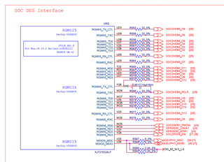
pdk_jacinto_07_01_00_45/packages/ti/board/src/j721e_evm/J721E_pinmux_data.c
static pinmuxPerCfg_t gVout0PinCfg[] =
{
/* MyVOUT1 -> VOUT1_DATA0 -> U23 */
{
PIN_RGMII5_TX_CTL, PIN_MODE(4) | \
((PIN_PULL_DISABLE) & (~PIN_PULL_DIRECTION & ~PIN_INPUT_ENABLE))
},
/* MyVOUT1 -> VOUT1_DATA1 -> U26 */
{
PIN_RGMII5_RX_CTL, PIN_MODE(4) | \
((PIN_PULL_DISABLE) & (~PIN_PULL_DIRECTION & ~PIN_INPUT_ENABLE))
},
/* MyVOUT1 -> VOUT1_DATA2 -> V28 */
{
PIN_RGMII5_TD3, PIN_MODE(4) | \
((PIN_PULL_DISABLE) & (~PIN_PULL_DIRECTION & ~PIN_INPUT_ENABLE))
},
/* MyVOUT1 -> VOUT1_DATA3 -> V29 */
{
PIN_RGMII5_TD2, PIN_MODE(4) | \
((PIN_PULL_DISABLE) & (~PIN_PULL_DIRECTION & ~PIN_INPUT_ENABLE))
},
/* MyVOUT1 -> VOUT1_DATA4 -> V27 */
{
PIN_RGMII5_TD1, PIN_MODE(4) | \
((PIN_PULL_DISABLE) & (~PIN_PULL_DIRECTION & ~PIN_INPUT_ENABLE))
},
/* MyVOUT1 -> VOUT1_DATA5 -> U28 */
{
PIN_RGMII5_TD0, PIN_MODE(4) | \
((PIN_PULL_DISABLE) & (~PIN_PULL_DIRECTION & ~PIN_INPUT_ENABLE))
},
/* MyVOUT1 -> VOUT1_DATA6 -> U29 */
{
PIN_RGMII5_TXC, PIN_MODE(4) | \
((PIN_PULL_DISABLE) & (~PIN_PULL_DIRECTION & ~PIN_INPUT_ENABLE))
},
/* MyVOUT1 -> VOUT1_DATA7 -> U25 */
{
PIN_RGMII5_RXC, PIN_MODE(4) | \
((PIN_PULL_DISABLE) & (~PIN_PULL_DIRECTION & ~PIN_INPUT_ENABLE))
},
/* MyVOUT1 -> VOUT1_DATA8 -> U27 */
{
PIN_RGMII5_RD3, PIN_MODE(4) | \
((PIN_PULL_DISABLE) & (~PIN_PULL_DIRECTION & ~PIN_INPUT_ENABLE))
},
/* MyVOUT1 -> VOUT1_DATA9 -> U24 */
{
PIN_RGMII5_RD2, PIN_MODE(4) | \
((PIN_PULL_DISABLE) & (~PIN_PULL_DIRECTION & ~PIN_INPUT_ENABLE))
},
/* MyVOUT1 -> VOUT1_DATA10 -> R23 */
{
PIN_RGMII5_RD1, PIN_MODE(4) | \
((PIN_PULL_DISABLE) & (~PIN_PULL_DIRECTION & ~PIN_INPUT_ENABLE))
},
/* MyVOUT1 -> VOUT1_DATA11 -> T23 */
{
PIN_RGMII5_RD0, PIN_MODE(4) | \
((PIN_PULL_DISABLE) & (~PIN_PULL_DIRECTION & ~PIN_INPUT_ENABLE))
},
/* MyVOUT1 -> VOUT1_DATA12 -> Y28 */
{
PIN_RGMII6_TX_CTL, PIN_MODE(4) | \
((PIN_PULL_DISABLE) & (~PIN_PULL_DIRECTION & ~PIN_INPUT_ENABLE))
},
/* MyVOUT1 -> VOUT1_DATA13 -> V23 */
{
PIN_RGMII6_RX_CTL, PIN_MODE(4) | \
((PIN_PULL_DISABLE) & (~PIN_PULL_DIRECTION & ~PIN_INPUT_ENABLE))
},
/* MyVOUT1 -> VOUT1_DATA14 -> W23 */
{
PIN_RGMII6_TD3, PIN_MODE(4) | \
((PIN_PULL_DISABLE) & (~PIN_PULL_DIRECTION & ~PIN_INPUT_ENABLE))
},
/* MyVOUT1 -> VOUT1_DATA15 -> W28 */
{
PIN_RGMII6_TD2, PIN_MODE(4) | \
((PIN_PULL_DISABLE) & (~PIN_PULL_DIRECTION & ~PIN_INPUT_ENABLE))
},
/* MyVOUT1 -> VOUT1_DE -> W26 */
{
PIN_RGMII6_RXC, PIN_MODE(4) | \
((PIN_PULL_DISABLE) & (~PIN_PULL_DIRECTION & ~PIN_INPUT_ENABLE))
},
/* MyVOUT1 -> VOUT1_HSYNC -> W27 */
{
PIN_RGMII6_TD0, PIN_MODE(4) | \
((PIN_PULL_DISABLE) & (~PIN_PULL_DIRECTION & ~PIN_INPUT_ENABLE))
},
/* MyVOUT1 -> VOUT1_PCLK -> W29 */
{
PIN_RGMII6_TXC, PIN_MODE(4) | \
((PIN_PULL_DISABLE) & (~PIN_PULL_DIRECTION & ~PIN_INPUT_ENABLE))
},
/* MyVOUT1 -> VOUT1_VSYNC -> V25 */
{
PIN_RGMII6_TD1, PIN_MODE(4) | \
((PIN_PULL_DISABLE) & (~PIN_PULL_DIRECTION & ~PIN_INPUT_ENABLE))
},
{PINMUX_END}
}

Looking forward to your reply, thanks a lot!

  • Add some information。

    I use qnx system. it's vision is pdk_jacinto_07_01_00_45.

    How to display normal in my board? is my config fit my board?

  • Hi,

    The DSS (Display SubSystem) driver can be controlled by the A72 or the R5 on the TDA4.  The Vision Apps framework can support either but defaults to the R5 control of the DSS.   

    The "gles2-gears" application runs with the assumption that the DSS driver is being controlled by A72.    

    Which location (A72 vs R5) the DSS is controlled from, is entirely up to the user, but the S/W must be configured accordingly. 

    See 5. PSDK QNX Components — Processor SDK QNX J721E (ti.com),  5.2.2. Enabling A72 Control of DSS,  for enabling A72 control of the A72. 

    If display driver is to be controlled by the R5, then one of the vision apps demos can be run, to test out the display.  The Vision Apps User Guide: Dense Optical Flow Application could be tried to see if HDMI output is functional

    Regards,

    kb  

  • Hi Kb,

    Thanks for your reply. i retest in my board, and update the result.

    1. I only find four macros, they are ENABLE_DSS_DUAL ENABLE_DSS_SINGLE ENABLE_DSS_HDMI and ENABLE_DSS_DSI, no this macro ENABLE_DSS in file app_cfg_mcu2_0.h
    And i also show my modify as above code.
    2. I use run_app_dof.sh script, HDMI still no output, and the CLK of adv7511 has no signal, but data2 has, data3 and data12 also no signal.
    3. In another version i use A72 control DSS, and test 'gles2-gears',  i find that CLK and data of adv7511 have signals, but HDMI is not output in the end.
    This version has some modify in default code. so i want to known is there a patch when use DPI-1 for output. If it is exist, please share me, Thanks

  • Hi xie jc,

    1. I only find four macros, they are ENABLE_DSS_DUAL ENABLE_DSS_SINGLE ENABLE_DSS_HDMI and ENABLE_DSS_DSI, no this macro ENABLE_DSS in file app_cfg_mcu2_0.h

    You would require to enable ENABLE_DSS_SINGLE and ENABLE_DSS_HDMI macros in the app_cfg_mcu2_0.h file. Other than this, the above changes look fine. 

    Regards,

    Brijesh

  • i had modified it as your advise. but it is no output in hdmi moniter. I see your test report in code project. it has DPI-1 test case.

    Is there any config besides my modify?

  • Hi xie jc,

    Can you please refer to below faq?

    https://e2e.ti.com/support/processors-group/processors/f/processors-forum/949461/faq-processor-sdk-dra8x-tda4x-how-to-enable-vout1-dpi1-output-in-vision-apps

    Are you enable DPI1 in embedded sync format or discrete sync format? Because embedded sync format is not supported on DPI1. 

    If you are using discrete sync format and it is still not working, can you please probe clk, hs, vs signals and see if they are toggling first? 

    Regards,

    Brijesh

  • Before modify the code as below. the data0~data15 pins has signals but HS,VS,DE no signals.
    vpEsParams.dvoFormat = APP_DCTRL_DV_BT1120_EMBSYNC;

    I modify it as below, i find that HS,VS, and DE has signals.

    vpEsParams.dvoFormat = APP_DCTRL_DV_GENERIC_DISCSYNC;
    Now i have a problem. by hw designe vout1 hava 16 ouputs, it is data0~data15, and it's encode is BT1120. But which parameter is difined it? now vout1 data has no signals. Is there anything need to config?

  • Hi xie jc,

    Sorry did not get your question, do you mean your receiving module expects bt1120 format? I think bt1120 format is not supported on vout1. 

    Regards,

    Brijesh

  • Are you enable DPI1 in embedded sync format or discrete sync format? Because embedded sync format is not supported on DPI1
    as your last advise, i modify dvoFormat to APP_DCTRL_DV_GENERIC_DISCSYNC, then HS,VS,DE has signals, but vout1 data0~data15 pins has no signals, and hdmi monitor also no image.
    in DPI1 inputs condition, we only want hdmi monitor can display, but now it not work.
    on my side,i find that if i only modify dvoFormat to APP_DCTRL_DV_BT1120_EMBSYNC, vout1 data0~data15 has signals, but HS,VS,DE no signal.
    i think maybe some something not correct in code.
    also i am not sure what is correct videoIfWidth. 12bit or 16bit is correct in my design?
    Looking forward to your reply, thanks a lot!

  • When you set the output format to APP_DCTRL_DV_BT1120_EMBSYNC, there will not be any sync signals, ie nothing on HS, VS and DE. 

    Could you please check if you require these signals or not? 

    If you require these signals, then please set the output format to APP_DCTRL_DV_GENERIC_DISCSYNC. If you are seeing signals in HS, VS and DE output signals, then the venc is started and is outputting data. can you also check if vs frequency is correct? In this case, can you please check if pinmux is setup correct? What is the background color you are setting in overlay manager. Can you set the some difference background color, like white, which will have all line high? 

    Regarding HDMI, i am not sure how HDMI is connected to DPI output. Does it require any configuration? 

    I would first suggest making sure that there is a data on the data lines, then check the HDMI output..

    Regards,

    Brijesh

  • Hi Brijesh Jadav,
    now hdmi connect is work, it will show background color, not display no signal.
    when i set to APP_DCTRL_DV_GENERIC_DISCSYNC, the frequece of VS is 57Hz, the frequece of HS is 43kHz, and DE also has signal. But DPI1 output0~output15 no signal.
    Is these frequeces correct?

    as your said "If you are seeing signals in HS, VS and DE output signals, then the venc is started and is outputting data."
    what will cause this thing happen? the display flow is DPI1->ADV7511->hdmi monitor, now ADV7511->hdmi is normal.so maybe something is wrong in TDA4 DPI1 setting.
    what is your opition about it?

    Looking forward to your reply, thanks a lot!

  • Hi xie jc,

    We are discussing same issue on the other thread, so closing this thread. Thank you.

    Regards,

    Brijesh