This thread has been locked.

If you have a related question, please click the "Ask a related question" button in the top right corner. The newly created question will be automatically linked to this question.

DRA829V: USB3.0 issues

Part Number: DRA829V

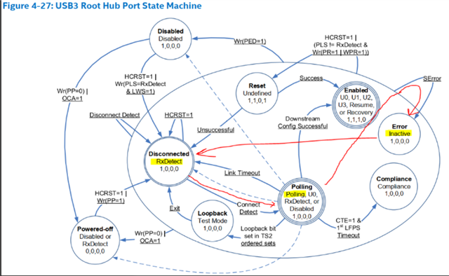
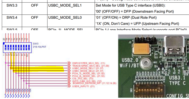
I am having trouble getting the USB3.0 host controller to connect with a device on a type C connector on USBSS1. The device will connect at HS but not SS. I am verifying that the clocks are set up correctly. 

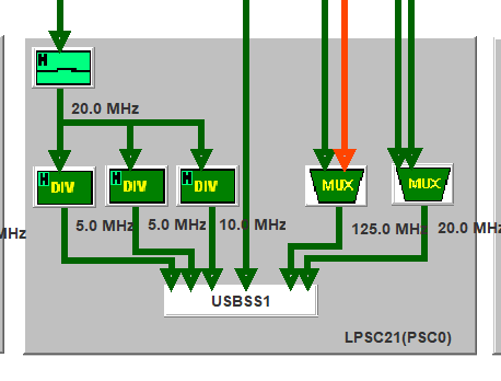
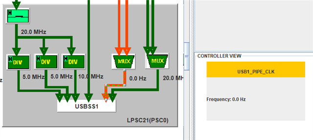
The Clock Tree Tool shows a clock called USB1_PIPE_CLK that is not enabled (red) but there is no documentation for this that I could find in the TRM. I am using SERDES1. 

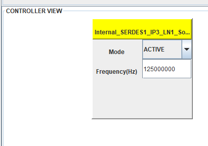
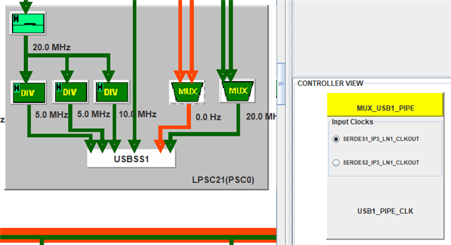
The Mux shows it is set up to choose the SERDES1_IP_LN1_CLKOUT

I will have more things to check on this thread but I want to verify the clocks are set up correctly first.

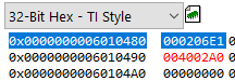
The CTT does not show ACLK either.

Where is USBSS1 ACLK in CTT?

What is USB1_PIPE_CLK in CTT?

  • Here is the SERDES1 in CTT:

  • Bill,

    Focusing on USB1_PIPE_CLK first, does the clock tree tool show the source of the 2 inputs to MUX_USB1_PIPE?  Is there a way to enable one of them?

    -Zack

  • in CTT, the source inputs to MUX_USB1_PIPE go to SERDES1_IP3_LN1_CLKOUT and SERDES2_IP3_LN1_CLKOUT. If you go to the Controller View for those clocks it shows mode Inactive. If you toggle to active then I think you need to specifiy a frequency but there's no documentation for these clocks that I could find in SPRUIJ7A. 

    As a test I changed Internal_SERDES1_IP_LN1_So... to Mode Active and set it to 125MHz (complete swag), then saved the CTT registers and compared that to my register dump that I got from the board over jtag. There were no diffs. 

  • If you disable that clock and then save the CTT registers, and diff them with the CTT registers with the clock enabled, is there a difference?  Also, what software is setting the registers on your board?

  • If you disable that clock and then save the CTT registers, and diff them with the CTT registers with the clock enabled, is there a difference? 

    no 

    Also, what software is setting the registers on your board?

    code from ti-processor-sdk-rtos-j721e-evm-07_03_00_07 

    I'm thinking USB1_PIPE_CLK might be a fake clock that just shows up in CTT.

  • Bill,

    That may be the case.  Or it may be that the register field governing this clock is not adequately captured by the CTT register outputs.  Either way before focusing on the clock issue, I'd like more background on the problem you're facing.  Are you running on an EVM or on custom hardware?  If the latter, what are the differences in the USB circuit schematics of your board versus the EVM?

    -Zack

  • Are you running on an EVM or on custom hardware?

    custom hardware

    what are the differences in the USB circuit schematics of your board versus the EVM?

    I emailed relavent section of the USB3 portion to Brad Caldwell

    I was seeing the USB2 xhci portsc transition to the connected state but the USB3 portsc went from link state RxDetect->Polling->Inactive->RxDetect with the PLC flag set. 

    We removed the surge suppresion components between the type C and the USB3 redriver and the behavior changed to never getting out of the RxDetect Disconnected state.

  • Also note that we are using USB3SS1 controller. I made a couple modifications to ti/drv/usb/soc/j721e/usb_wrapper.c:

    usb3_wrapper_config, disable USB2_ONLY_MODE if usb30Enabled is TRUE:

    The else clause was missing in the original SDK code:

    /* set to USB2.0 only if USB3.0 is not enabled. i.e SERDES is not used */
    if (usbConfig->usb30Enabled == FALSE) /* user asks for USB2.0 only */
    {
    HW_WR_FIELD32(usbCmnRegs + CSL_USB3P0SS_CMN_USB3P0SS_W1,
    CSL_USB3P0SS_CMN_USB3P0SS_W1_USB2_ONLY_MODE, 0x1);
    }
    else
    {
    HW_WR_FIELD32(usbCmnRegs + CSL_USB3P0SS_CMN_USB3P0SS_W1,
    CSL_USB3P0SS_CMN_USB3P0SS_W1_USB2_ONLY_MODE, 0x0);
    }

    And in usbClockSSCfg, enable Serdes if port is 1, added all this:

    if (portNumber == 1)
    {
    if (usbConfig->serdesId == 1)
    {
    CSL_FINS(*(uint32_t *)(uintptr_t)
    (CSL_CTRL_MMR0_CFG0_BASE + CSL_MAIN_CTRL_MMR_CFG0_USB1_CTRL),
    MAIN_CTRL_MMR_CFG0_USB1_CTRL_SERDES_SEL, 0x0); /* 0 is serdes 1, 1 is serdes 2 */

    CSL_FINS(*(uint32_t *)(CSL_CTRL_MMR0_CFG0_BASE + CSL_MAIN_CTRL_MMR_CFG0_SERDES1_CLKSEL),
    MAIN_CTRL_MMR_CFG0_SERDES1_CLKSEL_CORE_REFCLK_SEL,
    USB_MAIN_PLL2_HSDIV4_CLKOUT); /* 100MHz */

    CSL_FINS(*(uint32_t *)(CSL_CTRL_MMR0_CFG0_BASE + CSL_MAIN_CTRL_MMR_CFG0_SERDES1_CLK1SEL),
    MAIN_CTRL_MMR_CFG0_SERDES1_CLKSEL_CORE_REFCLK_SEL,
    USB_MAIN_PLL2_HSDIV4_CLKOUT); /* 100MHz */

    CSL_FINSR(*(volatile uint32_t *)(uintptr_t)
    (CSL_CTRL_MMR0_CFG0_BASE + CSL_MAIN_CTRL_MMR_CFG0_SERDES1_LN0_CTRL),1,0,0x2);

    CSL_FINSR(*(volatile uint32_t *)(uintptr_t)
    (CSL_CTRL_MMR0_CFG0_BASE + CSL_MAIN_CTRL_MMR_CFG0_SERDES1_LN1_CTRL),1,0,0x2);
    }

    }

  • are the above code changes correct?

  • on the evaluation board if I stop in u-boot the device connected to the type c is not detected and I'm getting errors from both root hub ports not able to get the phy with ret -61

    => usb start
    starting USB...
    Bus usb@6400000: cdns-usb3-host usb@6400000: Unable to get USB2 phy (ret -61)
    cdns-usb3-host usb@6400000: Unable to get USB3 phy (ret -61)
    cdns-usb3-host usb@6400000: DRD version v1 (ID: 0004024e, rev: 00000200)
    Register 2000840 NbrPorts 2
    Starting the controller
    USB XHCI 1.00
    scanning bus usb@6400000 for devices... 2 USB Device(s) found
    scanning usb for storage devices... 0 Storage Device(s) found

    also notice a discrepency in the documentation. here it shows usbc_mode_sel1 and 0 as sw3.3 and 4, but the schematic snippet shows them connected to switches 4 and 5. 

    I have 3,4 and 5 set to off and a usb thumb drive connected to the type c

  • I am seeing a lot of failures with the USB_HostMsc_usb30_j721e_evm_mpu1_0TestApp_debug.xa72fg

    It is not connecting to the usb3 root hub port all of the time. Sometimes it does but mostly not. 

    RTOS USB Host MSC example!!
    Enabling USB-C DIR detection
    
    IntConfig:  portNum[1],pinNum[3], bankNum=0, intNum[392][initCheckDidRidReg   5158    0]-Warning! DID, RID register pointers are not set.
    [initXhcSetupScratchP 4734    1]-<0> Reducing number of scratch pad to: 1
    
     Test in progress.
    [handleXhciCommadComp 3835    2]-<0> Command 11 failed, code: 4
    [commadCompletionEnab 3505    3]-<0> actualdeviceSlot (2) greater than max slots (2)
    [handleXhciCommadComp 3835    4]-<0> Command 11 failed, code: 4
    [handleXhciCommadComp 3835    5]-<0> Command 11 failed, code: 4
    [commadCompletionEnab 3505    6]-<0> actualdeviceSlot (2) greater than max slots (2)
    [handleXhciCommadComp 3835    7]-<0> Command 11 failed, code: 4
    [handleXhciCommadComp 3835    8]-<0> Command 11 failed, code: 4
    [commadCompletionEnab 3505    9]-<0> actualdeviceSlot (2) greater than max slots (2)
    [handleXhciCommadComp 3835   10]-<0> Command 11 failed, code: 4
    [handleXhciCommadComp 3835   11]-<0> Command 11 failed, code: 4
    

    It is connected to the usb2 hub when the above failed test happened and I stopped the debugger to view the xhci portsc registers