This thread has been locked.
If you have a related question, please click the "Ask a related question" button in the top right corner. The newly created question will be automatically linked to this question.
Hi,experts:
In the recent TDA4 project, after we configured a gpio in uboot dts, we measured it with a multimeter until it was always 0.5v low, and the gpio function we finally wanted to implement was configured to be high.
Please help to see if the configuration is correct? And how to configure PRG1_PRU1_GPO9 and PRG1_PRU1_GPO10 to be high in uboot dts?
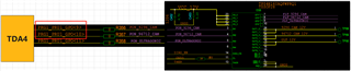
Here is a block diagram of the connection between the GPIO and TDA4 to be configured:
The following is the configuration of PRG1_PRU1_GPO9 and PRG1_PRU1_GPO10 in TDA4 uboot dts:
//k3-j721e-common-proc-board.dts sensor_power_n_pins_default: sensor_power_n-pins-default { pinctrl-single,pins = < J721E_IOPAD(0x7c, PIN_OUTPUT_PULLUP, 7) /* (AF21) PRG1_PRU1_GPO9.GPIO0_30 */ J721E_IOPAD(0x80, PIN_OUTPUT_PULLUP, 7) /* (AB23) PRG1_PRU1_GPO10.GPIO0_31 */ >; }; &main_gpio0 { pinctrl-names = "default"; pinctrl-0 = <&sensor_power_n_pins_default>; };
After gpio configuration, use a multimeter to measure 0 ohm resistance R356 and R357: the display is always 0.5
Using the gpio command in the uboot tool to see that the status is always low level 0, and the final gpio configuration I want is high level 1:
=> gpio status 30 30: input: 1 [ ] 30: input: 0 [ ] //(AF21) PRG1_PRU1_GPO9.GPIO0_30 30: input: 0 [ ] => gpio status 31 31: input: 0 [ ] 31: input: 0 [ ] //(AB23) PRG1_PRU1_GPO10.GPIO0_31 31: input: 0 [ ]
I originally wanted to use the 'gpio set' command to manually configure PRG1_PRU1_GPO9 and PRG1_PRU1_GPO10, but the 'gpio set 30' shows that the first one is executed, and I want to configure the second one:
=> gpio set 30 gpio: pin 30 (gpio 30) value is 1 => gpio status 30 30: output: 1 [ ] 30: input: 0 [ ] 30: input: 0 [ ]
The question asked is not very professional, I will try to improve it, thank you very much!
Hi,
if i understand correctly, You want to program PRG1_PRU1_GPO9 and PRG1_PRU1_GPO10 pins to gpio mode.
So the pinmux setting you have done below is not correct:
sensor_power_n_pins_default: sensor_power_n-pins-default {
pinctrl-single,pins = <
J721E_IOPAD(0x7c, PIN_OUTPUT_PULLUP, 7) /* (AF21) PRG1_PRU1_GPO9.GPIO0_30 */
J721E_IOPAD(0x80, PIN_OUTPUT_PULLUP, 7) /* (AB23) PRG1_PRU1_GPO10.GPIO0_31 */
>;
};
Please change it to below:
/* This file was auto-generated by TI PinMux on 3/14/2022 at 7:11:07 AM. */
/* This file should only be used as a reference. Some pins/peripherals, */
/* depending on your use case, may need additional configuration. */
&main_pmx0 {
mygpio1_pins_default: mygpio1_pins_default {
pinctrl-single,pins = <
J721E_IOPAD(0x7c, PIN_INPUT, 7) /* (AF21) PRG1_PRU1_GPO9.GPIO0_30 */
J721E_IOPAD(0x80, PIN_INPUT, 7) /* (AB23) PRG1_PRU1_GPO10.GPIO0_31 */
>;
};
};
Best Regards,
Keerthy
Hi Keerthy:
Thank you for your quick reply, according to your configuration method, I updated the configuration as follows:
&main_pmx0 { sensor_power_n_pins_default: sensor_power_n-pins-default { pinctrl-single,pins = < J721E_IOPAD(0x7c, PIN_OUTPUT_PULLUP, 7) /* (AF21) PRG1_PRU1_GPO9.GPIO0_30 */ J721E_IOPAD(0x80, PIN_OUTPUT_PULLUP, 7) /* (AB23) PRG1_PRU1_GPO10.GPIO0_31 */ >; }; }; &main_gpio0 { pinctrl-names = "default"; pinctrl-0 = <&sensor_power_n_pins_default>; };
The measurement result by the multimeter shows that it is always 0.5v. How to configure GPIO_30 and GPIO_31 in uboot dts and output high level? Can I use the uboot 'gpio' command to query the gpio status after configuration?
Thanks for your support!
Hi,
Can you please carefully look at the config?
J721E_IOPAD(0x7c, PIN_INPUT, 7) /* (AF21) PRG1_PRU1_GPO9.GPIO0_30 */
J721E_IOPAD(0x80, PIN_INPUT, 7) /* (AB23) PRG1_PRU1_GPO10.GPIO0_31 */
You are still configuring pins as output while it should be input.
- Keerthy
Hi Keerthy:
Thank you for your quick reply, I confirm that the configuration method you mentioned has been tried, and the test results are the same. I have the XDS560v2 debugger in hand, if there is a CCS related method to configure and verify the configuration of the GPIO, I am also very willing to try it.
Can I directly use the command tool that comes with uboot to manually configure the level of GPIO?
e.g:
=> gpio gpio - query and control gpio pins Usage: gpio <input|set|clear|toggle> <pin> - input/set/clear/toggle the specified pin gpio status [-a] [<bank> | <pin>] - show [all/claimed] GPIOs
Thank you very much for your support!
Hi,
With gpio you can only toggle the state of GPIO registers but the physical line can only toggle if your pinmux is correct.
Can you dump the values from U-Boot prompt using md command:
md 0x11c07c
md 0x11c080
I want to verify if indeed the pin muxing has taken effect.
Regards,
Keerthy
Hi Keerthy:
Very sorry to reply you so late, thank you for your quick reply.
The following is my configuration for GPIO0_30, GPIO0_31 in uboot dts:
&main_pmx0 { sensor_power_n_pins_default: sensor_power_n-pins-default { pinctrl-single,pins = < J721E_IOPAD(0x7c, PIN_INPUT, 7) /* (AF21) PRG1_PRU1_GPO9.GPIO0_30 */ J721E_IOPAD(0x80, PIN_INPUT, 7) /* (AB23) PRG1_PRU1_GPO10.GPIO0_31 */ >; }; }; &main_gpio0 { pinctrl-names = "default"; pinctrl-0 = <&sensor_power_n_pins_default>; };
According to your guidance method, I performed the corresponding operations, and the results are as follows:
=> md 0x11c07c 0011c07c: 00050007 00050007 08214007 08214007 .........@!..@!. 0011c08c: 08214007 08214007 08214007 08214007 .@!..@!..@!..@!. 0011c09c: 08254007 08214007 08214007 08214007 .@%..@!..@!..@!. 0011c0ac: 08214007 08214007 00010007 08214007 .@!..@!......@!. 0011c0bc: 08214007 08214007 08254007 08214007 .@!..@!..@%..@!. 0011c0cc: 08214007 08214007 08214007 08214007 .@!..@!..@!..@!. 0011c0dc: 08214007 08214007 08214007 08214007 .@!..@!..@!..@!. 0011c0ec: 08214007 08214007 08254007 08214007 .@!..@!..@%..@!. 0011c0fc: 08214007 08214007 08214007 08214007 .@!..@!..@!..@!. 0011c10c: 08214007 08214007 08254007 08214007 .@!..@!..@%..@!. 0011c11c: 08214007 08214007 08214007 08214007 .@!..@!..@!..@!. 0011c12c: 08214007 08214007 08214007 08214007 .@!..@!..@!..@!. 0011c13c: 08214007 08214007 08254007 08214007 .@!..@!..@%..@!. 0011c14c: 08214007 08214007 08214007 08214007 .@!..@!..@!..@!. 0011c15c: 08214007 08214007 08214007 08214007 .@!..@!..@!..@!. 0011c16c: 08214007 08214007 08214007 08214007 .@!..@!..@!..@!. => md 0x11c080 0011c080: 00050007 08214007 08214007 08214007 .....@!..@!..@!. 0011c090: 08214007 08214007 08214007 08254007 .@!..@!..@!..@%. 0011c0a0: 08214007 08214007 08214007 08214007 .@!..@!..@!..@!. 0011c0b0: 08214007 00010007 08214007 08214007 .@!......@!..@!. 0011c0c0: 08214007 08254007 08214007 08214007 .@!..@%..@!..@!. 0011c0d0: 08214007 08214007 08214007 08214007 .@!..@!..@!..@!. 0011c0e0: 08214007 08214007 08214007 08214007 .@!..@!..@!..@!. 0011c0f0: 08214007 08254007 08214007 08214007 .@!..@%..@!..@!. 0011c100: 08214007 08214007 08214007 08214007 .@!..@!..@!..@!. 0011c110: 08214007 08254007 08214007 08214007 .@!..@%..@!..@!. 0011c120: 08214007 08214007 08214007 08214007 .@!..@!..@!..@!. 0011c130: 08214007 08214007 08214007 08214007 .@!..@!..@!..@!. 0011c140: 08214007 08254007 08214007 08214007 .@!..@%..@!..@!. 0011c150: 08214007 08214007 08214007 08214007 .@!..@!..@!..@!. 0011c160: 08214007 08214007 08214007 08214007 .@!..@!..@!..@!. 0011c170: 08214007 08214007 08214007 08214007 .@!..@!..@!..@!.
The result measured by the multimeter shows that the level is still low. I don't know where the problem is. Do you have any more suggestions for this problem?
Thank you for your support!
Hi,
The pinmux value is correct now. Since you are trying to set GPIO0_30 & GPIO0_31
You can check the value of the GPIO via the register: GPIO_OUT_DATA01 Address: 0x600014
I am giving direct register writes to configure the GPIO0_30 & GPIO0_31 to output direction and set the value to high:
mw 0x600010 0x3FFFFFFF 1 /* This sets the bit30/31 to 0 & hence direction is output */
mw 0x600014 0xC0000000 1 /* This sets the bit30/31 to 1 & hence value is HIGH */
Please measure the value and let me know.
- Keerthy
Hi,Keerthy:
Thanks for your support, now GPIO can control the output.
=> mw 0x600010 0x3FFFFFFF 1 => mw 0x600014 0xC0000000 1 => i2c dev 3 Setting bus to 3 => i2c probe Valid chip addresses: 29 40 48 => gpio status 30 30: input: 1 [ ] 30: output: 1 [ ] 30: input: 0 [ ] => gpio status 31 31: input: 0 [ ] 31: output: 1 [ ] 31: input: 0 [ ]
Thanks!