This thread has been locked.

If you have a related question, please click the "Ask a related question" button in the top right corner. The newly created question will be automatically linked to this question.

TDA4VM: VPAC LDC Node and LUT

Part Number: TDA4VM

Hello,

I have created customized LUT with a different algorithm (using distortion correction coefficients) in C++. It works well when I test it in C++ but when I test that LUT in PSDK 7.1 . The results are totally different. I have created LUT similar to the format of TI LUT as shown below.
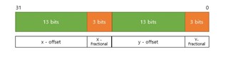
My question is ,

Is this the correct format of mesh LUT?

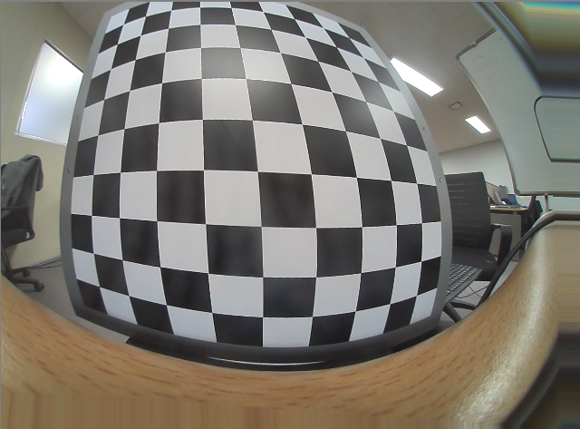
Is there any transformation (geometric or perspective) happening inside tivxVpacLdc Node? which is unwrapping the image rather than making it cylindrical as you can see in the resultant output image I am getting?

how VpacLdcNode is processing the LUT ?

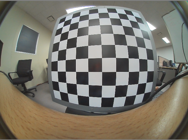
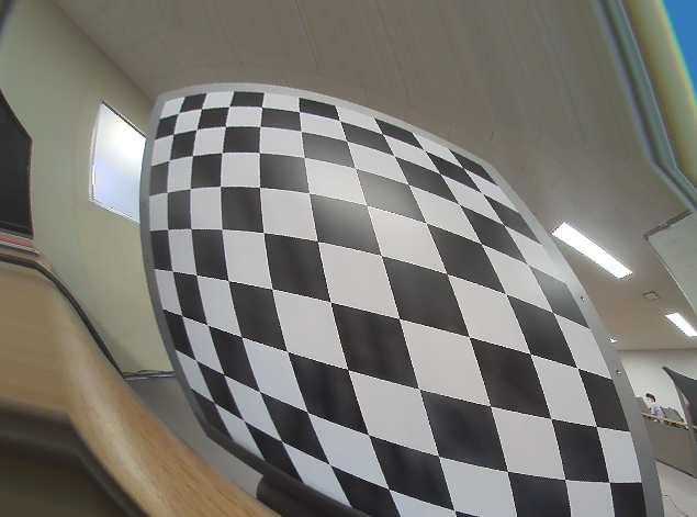
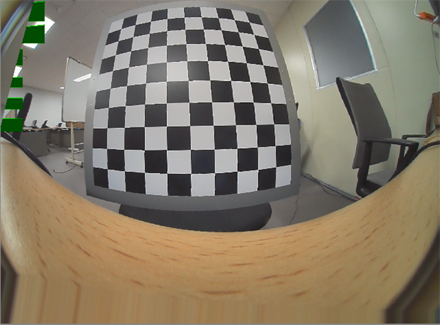
this is the input image I have captured  from camera for testing.


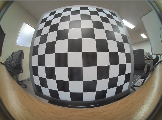
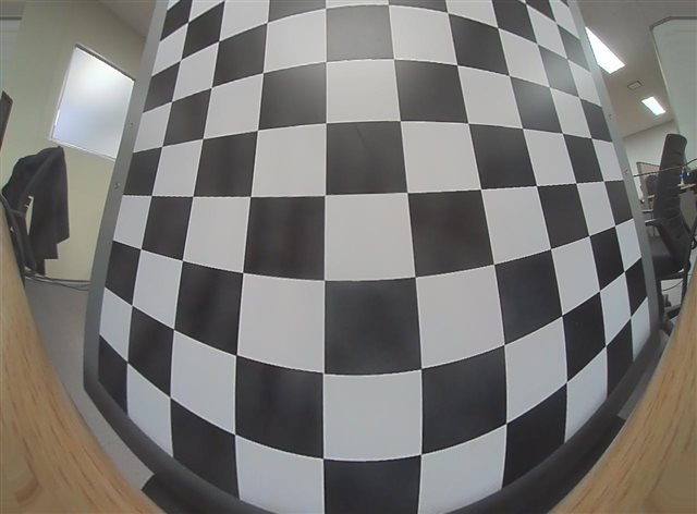
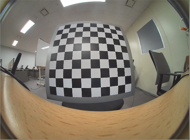
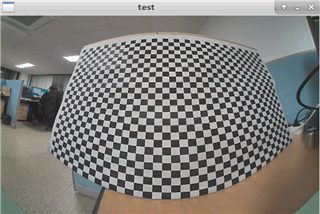
this is the desired output 

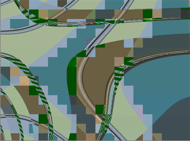
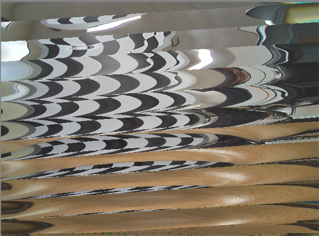
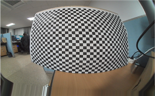
The image I am getting from (app_single_camera) for LUT I have generated


Note: I am not downsampling my LUT so I kept the downsampling factor as 1 

I have made the following changes in the app_single_camera to remove downsampling 

#define LDC_TABLE_WIDTH  (1280)
#define LDC_TABLE_HEIGHT (944)
#define LDC_DS_FACTOR     (1)
#define LDC_BLOCK_WIDTH   (8)
#define LDC_BLOCK_HEIGHT  (2)
#define LDC_PIXEL_PAD     (1)


table_width = 1280;
table_height = 944;

/* Mesh Image */
obj->mesh_img = vxCreateImage(obj->context,table_width, table_height, VX_DF_IMAGE_U32);

vxCopyImagePatch(obj->mesh_img, &rect, 0, &image_addr,
                ldc_lut, VX_WRITE_ONLY, VX_MEMORY_TYPE_HOST);
                
 obj->mesh_params.mesh_frame_width = 1280;
 obj->mesh_params.mesh_frame_height = 944;
 obj->mesh_params.subsample_factor = 1
 
 
I am attaching LUT header file I have created for clear understanding. Please let me know if there is anything wrong in the header file i have created 
This is the code from which I have generated LUT file similar to TI LUT format

// make lut

// find offset for x, y coordinate
dx = fix - x;     // distorted x - input x
dy = fiy - y;     // distorted y - input y

// fractional
weight_x = (8.0f * dx) & 0x7;
weight_y = (8.0f * dy) & 0x7;

qx = (int)dx;
qy = (int)dy;

xp = ((qx << 3) & 0xFFF8); // | (weight_x & 0x07);
yp = ((qy << 3) & 0xFFF8); // | (weight_y & 0x07);

//output data for one pixel
val_encode = ((xp << 16) & 0xFFFF0000) | (yp & 0xFFFF);

bilinear_table[y*outWidth + x] = val_encode;

//print 

 FILE *fp = fopen("LUT_TI.h","wt");
  
            int i = 0;

            // make header
            fprintf(fp, "#ifndef ISXO16_UB9BA_Q1_DCC_H_\n");
            fprintf(fp, "#define ISXO16_UB9BA_Q1_DCC_H_\n\n");
            fprintf(fp, "#define ISXO16_UB9BA_Q1_DCC_CFG_NUM_ELEM	(%du)\n\n", outWidth*outHeight*4);
            fprintf(fp, "#define ISXO16_UB9BA_Q1DCC_CFG \\\n{\\\n    ");

            // store items
            for (i = 0; i<outWidth*outHeight-1; i++)
            {
                fprintf(fp, "0x%02x, ", bilinear_table[i] & 0xFF);
                fprintf(fp, "0x%02x, ", (bilinear_table[i] >> 8) & 0xFF);
                fprintf(fp, "0x%02x, ", (bilinear_table[i] >> 16) & 0xFF);
                fprintf(fp, "0x%02x, ", (bilinear_table[i] >> 24) & 0xFF);
                if(i%4 == 3) fprintf(fp, "\\\n    ");
            }
            // last item
            fprintf(fp, "0x%02x, ", bilinear_table[i-1] & 0xFF);
            fprintf(fp, "0x%02x, ", (bilinear_table[i-1] >> 8) & 0xFF);
            fprintf(fp, "0x%02x, ", (bilinear_table[i-1] >> 16) & 0xFF);
            fprintf(fp, "0x%02x \\\n}\n\n#endif  /* End of #ifndef ISXO16_UB9BA_Q1_DCC_H_ */\n", (bilinear_table[i-1] >> 24) & 0xFF);
            fclose(fp);
      

Kind regards, 

Myrah Naeem

  • Hi,

    It looks like you might have the wrong order of x and y offsets (endianness).

    Please check the example given at the end of the FAQ: e2e.ti.com/.../faq-tda4vm-how-to-create-a-ldc-mesh-lut-for-fisheye-distortion-correction-on-tda4

    >> For example, the first row in "mesh.txt" above is "1818 (0x71a), 1341 (0x53d)", and the corresponding 32-bit binary word is "0x53d, 0x71a" in "test_mesh_lut.txt".

  • Thank you very much Gang,

    I will try that and get back to you if it wont work. 

    Kind Regards,

    Myrah Naeem

  • Hello Gang,

    I have reversed the order of coordinates like you have mentioned in the link . I am attaching the the LUT header file i have tested and the result I obtained after changing the order. Please check the LUT i have attached. Thank you 

    Original Image :


    Resultant Image:

    Kind Regards,

    Myrah Naeem

    LUT with positions according to TI format

    LUT_TI_REV.h

  • Hi Myrah,

    You did not reverse the order of H and V offsets.

    "LUT_TI.h"

        0x95, 0x02, 0x43, 0x03, ...

    "LUT_TI_REV.h"

        0x02, 0x95, 0x03, 0x43, ...

    to try:

        0x43, 0x03, 0x95, 0x02, ...

  • Hello Gang,

    I even tried this order but the result is not correct. I am attaching the LUT header file and resultant image i have obtained 

    "LUT_TI_REVERSE"

    0x43, 0x03, 0x95, 0x02, ..

    LUT_TI_REVERSE.h

    INPUT IMAGE

    RESULTANT IMAGE 

    Kind Regards,

    Myrah Naeem

  • OK, this looks like the right encoding format at least.

    You mentioned above:

    >>> "I am not downsampling my LUT so I kept the downsampling factor as 1"

    >>> "obj->mesh_params.subsample_factor = 1"

    This "subsample_factor" is m = 0, 1, 2, ..., 8 for 1x, 2x, 4x, ..., 128x down sampling.
    So, you should use 0 for no down sampling.
    Typically, you should not get valid output if you use 1 instead of 0.

    Please try 0 and let me know the result.

    BTW, "m" shall be at least 3 or 4 for real applications and smaller values are only for debugging and testing purposes.

  • Thank you very much gang for helping me out. 

    I kept LDC FACTOR = 0 

    >>> "obj->mesh_params.subsample_factor = 0"

    The output image is attached below and the error I received at the terminal was 

     VX_ZONE_ERROR :[tivxVpacLdcProcess:363] failed to submit Request

    Resultant Image :

    Thanks and Regards,

    Myrah Naeem

  • Hi Myrah,

    Interesting: I see how it could work with 1 in wrong geometry, but I don't understand what is wrong with 0.

    If you keep it as 1 and down sample your current 1280x944 LUT by 2x2 to get a 640x472 LUT, and replace the top-left 640x472 corner of your current LUT with this down sampled one, you shall get correct geometry.
    Can you try that so that we can verify your geometry first?

    Best,
    Gang

  • Hi Myrah,

    What is the output block size you are using for this experiment? 

    Regards,

    Brijesh

  • Thank you Gang, I have not understood this part "replace the top-left 640x472 corner of your current LUT with this down sampled one" can you please elaborate?

    Secondly, while creating the mesh image i changed value of table width and height. So I tested it again with original table width and table height and the result is valid .I am posting results of both. 

    Amended (table_width, table_height values) with LDC FACTOR = 0 :

    table_width = 1280;
    table_height =944;                                                                                                                                                                                                                                         

    obj->mesh_img = vxCreateImage(obj->context, table_width, table_height, VX_DF_IMAGE_U32);

    Original (table_width, table_height values) with LDC FACTOR  = 0  :

    table_width = (((obj->table_width / (1 << obj->ds_factor)) + 1u) + 15u) & (~15u);
    table_height = ((obj->table_height / (1 << obj->ds_factor)) + 1u);
    obj->mesh_img = vxCreateImage(obj->context, table_width, table_height, VX_DF_IMAGE_U32);

    Kind Regards,

    Myrah Naeem

  • Hello Brijesh,

    I tried with these parameters. 

    #define LDC_BLOCK_WIDTH (8)
    #define LDC_BLOCK_HEIGHT (2)
    #define LDC_PIXEL_PAD (1) 

    I also put region parameters as NULL in tivxVpacNode  but it had no effect on the image.

  • Hello Myrah,

    Can you put breakpoint on CSL_ldcCheckCfg API using CCS and see which error condition is failing? could try after checking out Gang's suggestion.

    Rgds,

    Brijesh

  • Hello Brijesh,

    Sure, I will try gang's suggestion and then yours. Then i will get back to you with error.

    Thanks and regards,

    Myrah

  • Hi Myrah,

    In your earlier code with "m=1" (and valid output image), LDC only used the top-left corner (640x472) of your 1280x944 LUT.
    I guess it works because all sizes are correct.

    output image: 1280x944
    frame size: 1280x944
    mesh LUT row width: 1280*4 bytes (mesh_img 1280x944)

    If you replace the top-left 640x472 with your 2x2 down sampled LUT (640*4 bytes wide) and keep m=1, LDC shall work with m=1 LUT properly.
    In that way, we can see if your geometry is correct.

    In your above output, it looks some size is still wrong with m=0.
    Since your mesh_img becomes 1296x944, you LUT shall be in 1296x944 (1296*4 bytes per row).

    Best,
    Gang

  • Hello Gang,

    thank you very much gang. I have understood your point. I will implement it as soon as possible and get back to you with the results .

    Kind Regards,

    Myrah

  • Hello Gang,

    I replaced top left 640x472 with my down sampled LUT with m= 1

    I am attaching LUT I have created and the resultant image i have obtained. Please check it and let me know if i have implemented the way you have suggested.

    LUT (with top-left replaced) :

    LUT_TI_top_left.h

    Resultant Image : 

    Kind Regards,

    Myrah Naeem

  • Hi Myrah,

    Could you please share your original input image and original offsets with which you can get the correct output image?

    Best,
    Gang

  • Hello Gang,

    This is my original input image in YUV 422 format.

    original_image.zip

    These are my offsets.

    PCA_OFFSETS.txt

    Thanks and Regards,

    Myrah Naeem

  • Hi Myrah,

    "PCA_OFFSETS.txt" has a wrong geometry if it is in LDC offset encoding format.

    With the below 2 lines as examples, could you please explain how you get those 4 numbers?

        line 001:     316 69

        line 700:    -16 69

    Line 1 is for output pixel at (H=0, V=0) and line 700 is for output pixel at (H=699, V=0).

    What are your expected pixel locations in the input image for these 2 output pixel locations?

    Best,
    Gang

  • Hello, Myrah,

          I just have a doubt about your file, in  LUT_Ti.h , the first 2 element is :

     <0xa1, 0x01>   <0x4a, 0x01> as your rules : the high 13 bit  represent offset and the lower 3 bit represent. then the 2 offset value is 110100  , and 101001 binary,  but in your PCA_OFFSETS.txt,  the first 2 value  is 316 and 69. 
        Even by your convert code, I can't convert these 2 value. Is there any problem here ?


  • Hello Gang ,

    I have saved data in the text file that is attached "PDA_data.txt"

    column 1 : x and y are initial positions of pixel,

    column 2 : fix and fiy are output pixel positions,

    column 3 : dx and dy are offsets which are calculated like this 

                     dx = fix - (float)x; 
                     dy = fiy - (float)y; 
    column 4 : hexadecimal of value which is saved in the LUT_TI.h. It is calculated like this 
                    weight_x = (unsigned char)(8.0f * dx) & 0x7;
                    weight_y = (unsigned char)(8.0f * dy) & 0x7;

                    qx = (int)dx;
                    qy = (int)dy;

                   xp = ((qx << 3) & 0xFFF8);
                   yp = ((qy << 3) & 0xFFF8);

                   value= ((yp << 16) & 0xFFFF0000) | (xp & 0xFFFF);
                   lut_table[i] = value;
                   Note: lut_table array is saved in the LUT_TI.h
    some extrinsic parameters are changed in the code so i am attaching the new LUT_TI.h
    Thank you and Regards,
    Myrah Naeem
  • Hi Myrah,

    Column 2 for fix and fiy may have issues.

    1. column 2 has wrong geometry overall.
    2. column 2 are all integers.
    3. column 2 has a lot of out of input image boundary locations.

    For example, Pixel at [0,0] in LDC output image is at [982, 78] in LDC input image.
    Do you think that is correct?

        [x y] [fix fiy] [dx dy], [lut_table]
        [0 0],[982 78], [982 78],[0x00, 0x00, 0x00, 0x00]
        [1 0],[982 78], [981 78],[0x00, 0x00, 0x00, 0x00]

  • Hello Gang, 

    Sorry I made a mistake and uploaded the wrong file. Please refer to the following one.

    8055.PCA_data.zip

    Kind Regards,

    Myrah Naeem

  • Hi Myrah,

    This picture above is what your output should look like given your LUT.
    Is it correct?

    In you "PCA_data.txt", you need to ensure "0 <= fix <= 1279" and "0<=fiy<=943" (you have some out of the image boundary).

    Best,
    Gang

  • yes gang, my output should be exactly like the image you have posted. I will put the limits and test that LUT in single camera application. Then i will let you know the results.

    Thanks and Regards,

    Myrah Naeem

  • Hello Gang,

    I tried to set the boundaries but I am still not getting the exact image.

    Can you please upload your pixel positions and LUT.h ?

    And can you please let me know any parameters changes like pixel padding, block width and block height?

    Kind Regards,

    Myrah Naeem

  • Hi Myrah,

    I only used your PCA_data.txt file to verify your geometry.

    Now you have confirmed your geometry is correct and you need to fix the boundary issue of your LUT.

    Adjacent LUT entries must be close by (e.g., fix and fiy getting out of image boundary) to avoid running out of LDC internal memory.

    Once you fix that, tuning tool can give your good block parameters (then you shall go to a higher LUT down sampling rate such as 16x16 or 8x8).

    Best,
    Gang

  • Hello Gang,

    Firstly, I tried to set boundaries and create LUT without using DCC tool to get block parameters. I used the previous block parameters but the resultant image I am getting is still not the one we require. Can you please check this code and these parameters and guide me about where I am making the mistake?

    Secondly, you wrote "Adjacent LUT entries must be close by". Can you please explain what do you mean by this ? And what should be the adjacent values for out of boundary fix and fiy 

    I tried 2 conditions one by one but neither of them worked and their results are same

    // condition to set boundries
    
    //CONDITION 1 
    
             if(fix >= 1279)
            {
            fix = 1279 ;
            } 
            
            if(fiy >= 943)
            {
            fiy = 943;
            }
            
            if(fix <=0)
            {
            fix = 0 ;
            }
            
            if(fiy <=0)
            {
            fiy = 0 ;
            }
            
    //CONDITION 2
    
            if(( 0 <= fiy && fiy <= 943) && (0 <= fix && fix <= 1279))
            {
            fiy = fiy ;
            fix = fix;
            }
            else 
            {
            fiy = 0;
            fix = 0;
            }

    After setting conditions i used the following code :

    //make LUT
    
    // find offset for x, y coordinate
    dx = fix - x;     // distorted x - input x
    dy = fiy - y;     // distorted y - input y
    
    // fractional
    weight_x = (8.0f * dx) & 0x7;
    weight_y = (8.0f * dy) & 0x7;
    
    qx = (int)dx;
    qy = (int)dy;
    
    xp = ((qx << 3) & 0xFFF8); // | (weight_x & 0x07);
    yp = ((qy << 3) & 0xFFF8); // | (weight_y & 0x07);
    
    //output data for one pixel
    val_encode = ((xp << 16) & 0xFFFF0000) | (yp & 0xFFFF);
    
    bilinear_table[y*outWidth + x] = val_encode;
    
    //print 
    
     FILE *fp = fopen("LUT_TI.h","wt");
      
                int i = 0;
    
                // make header
                fprintf(fp, "#ifndef ISXO16_UB9BA_Q1_DCC_H_\n");
                fprintf(fp, "#define ISXO16_UB9BA_Q1_DCC_H_\n\n");
                fprintf(fp, "#define ISXO16_UB9BA_Q1_DCC_CFG_NUM_ELEM	(%du)\n\n", outWidth*outHeight*4);
                fprintf(fp, "#define ISXO16_UB9BA_Q1DCC_CFG \\\n{\\\n    ");
    
                // store items
                for (i = 0; i<outWidth*outHeight-1; i++)
                {
                    fprintf(fp, "0x%02x, ", bilinear_table[i] & 0xFF);
                    fprintf(fp, "0x%02x, ", (bilinear_table[i] >> 8) & 0xFF);
                    fprintf(fp, "0x%02x, ", (bilinear_table[i] >> 16) & 0xFF);
                    fprintf(fp, "0x%02x, ", (bilinear_table[i] >> 24) & 0xFF);
                    if(i%4 == 3) fprintf(fp, "\\\n    ");
                }
                // last item
                fprintf(fp, "0x%02x, ", bilinear_table[i-1] & 0xFF);
                fprintf(fp, "0x%02x, ", (bilinear_table[i-1] >> 8) & 0xFF);
                fprintf(fp, "0x%02x, ", (bilinear_table[i-1] >> 16) & 0xFF);
                fprintf(fp, "0x%02x \\\n}\n\n#endif  /* End of #ifndef ISXO16_UB9BA_Q1_DCC_H_ */\n", (bilinear_table[i-1] >> 24) & 0xFF);
                fclose(fp);

    LUT header file for Condition 1:

    LUT_TI.zip

    LUT header file for Condition 2:

    ORI_LUT.zip

    Image captured from camera :

    Resultant Image (results for both conditions are same) : 

    Block Parameters : 

    #define LDC_TABLE_WIDTH (1280)
    #define LDC_TABLE_HEIGHT (944)
    #define LDC_DS_FACTOR (1)
    #define LDC_BLOCK_WIDTH (8)
    #define LDC_BLOCK_HEIGHT (2)
    #define LDC_PIXEL_PAD (1)

    Kind Regards,

    Myrah Naeem

  • Hello, Myrah,

              I am an engineer who is also developing a similar task with you. So we can discuss in this  post.

               I read your 8055.PCA_data.zip and find 1 problem and 2 doubt 

    problem 1:

    for your c code to convert lut,  this line have problem 

    xp = ((qx << 3) & 0xFFF8); // | (weight_x & 0x07);
    yp = ((qy << 3) & 0xFFF8); // | (weight_y & 0x07);

    it should be 

    xp = ((qx << 3) & 0xFFF8) | weight_x ;
    yp = ((qy << 3) & 0xFFF8)| weight_y ; 

    otherwise, the fraction  in  your lut, is always 0  (please review your PCA_data.txt)

    doubt 1;

    in your  PCA_data.txt, for every point such as [0xc8, 0x02, 0xd0, 0x02],  your put offset X then offset Y.

    but as Gang He's feed back 30 days ago, he mentioned  it should be Y offset then X offset.

    I'm not sure which one is correct, because in the tiovx guideline, it only say. 

    • 32bit encoding format (X,Y) is as follows:

    so maybe you can have a try for different way 

    doubt2:

    your input image size is 1280*944, and LDC_DS_FACTOR = 1 , so as the tiovx guideline(TIVX_VPAC_LDC_CALC_MESH_LINE_OFFSET.), the mesh image width and height shall be 

    table_width_ds = (((ldcObj->table_width / (1 << ldcObj->ds_factor)) + 1u) + 15u) & (~15u);       // 656
    table_height_ds = ((ldcObj->table_height / (1 << ldcObj->ds_factor)) + 1u);           //  473
     
    so lut size shall be 656*473*4,   but not 1280*944*4


  • Hello, Gang,

           I am a developer who is also meet similar problem with Myrah.

           I review this post's history and read the tiovx guideline/ sdk demo.

           I have a big doubt:

    as Myrah's example,  the input image is 1280*944 and the output image size is also 1280*944.

    as the tiovx guideline "he pitch/line offset for the mesh can be calculated using TIVX_VPAC_LDC_CALC_MESH_LINE_OFFSET. " and the demo code in "app_ldc_module.c",  we can see the width and height if the mesh table shall be 

    table_width_ds = (((ldcObj->table_width / (1 << ldcObj->ds_factor)) + 1u) + 15u) & (~15u);
    table_height_ds = ((ldcObj->table_height / (1 << ldcObj->ds_factor)) + 1u);
    ds_factor is not able to set to 0 (I try it in hardware, it is not allow), but is can be set as 1 (Myrah's setup is also 1 ).
    Then in his case, table_width_ds = 656   table_height_ds =473
    Now, here is the problem:
         As this process, we can see the LDC work process is
        1280*944 input   ->    based 656*473 mesh  - > 1280*944 output ,
         here we can see, obviously the mesh table will not set every point's offset relationship in the input image. 
         Then how can we select the 656*473 point from the 1280*944 point?
    Here is my guess:
    For example, the input image is 5*3, the pixel can be write as 
    p00 p01 p02 p03 p04
    p10 p11 p12 p13 p14
    p20 p21 p22 p23 p24
    the if ds_factor = 1, the mesh size shall be width = ( 5/2 + 1+ 15) & ~15 = (3 + 15) & ~15   height =  3/2 +1
    lets ignore " +15) & ~15", it is only for memory alignment, just set them as 0
    then we shall select a mesh table as 3 * 2
    so the mesh table shall select the point is:
    p00        p02        p04
    p20        p22         p24
     
    Am I right ?
  • Hi Wei,

    You can find the answers in the FAQ here: https://e2e.ti.com/support/processors-group/processors/f/processors-forum/1058565/faq-tda4vm-how-to-create-a-ldc-mesh-lut-for-fisheye-distortion-correction-on-tda4?tisearch=e2e-sitesearch&keymatch=TDA4%2520LDC%2520FAQ#
    It is a complete example with all details included.
    If you follow the FAQ step by step, you don't need to guess.

    Mesh LUT size is also in the code in the FAQ (similarly mesh down sampling is also covered in the matlab/octave code).

    Wmesh = ceil(W / 2^m) * 2^m;
    Hmesh = ceil(H / 2^m) * 2^m;

    Padding of the LUT on the right side for row alignment is explained with the example in step 4.

  • Hi Myrah,

    >> "Adjacent LUT entries must be close by"

    There are issues in the left 52 columns of your previous 1280x944 LUT.
    The locations of (fix, fiy) for them jump around the image (discontinuous) from top left to bottom left to top right corners of the images in a single column.
    You need to fix out of image border issues as well as this discontinuity issue.
    This is a common problem when (fix, fiy) are generated without taking care of boundary conditions in the geometrical mapping.

    So, the first step is to get valid (fix, fiy) for all locations.

    Then, the second step is to get a valid LUT including down-sampling, integer encoding, and row alignment.
    You can follow the FAQ to get this done.

    The 3rd step is to use your LUT (tuning tool requires LUT in the matlab output format) to find the proper block parameters (LUT must be down-sampled for this to be meaningful).

    The last step is to program everything into H/W and test.

  • Hello Gang,

    Firstly, I have analyzed the whole "PCA_data.txt" and "LUT_TI.h" but I have not found the discontinuity problem or Maybe I have not understood what do you mean by discontinuity. So, can you please explain which 52 columns are discontinuous and how they should be corrected? 

    Secondly, I have already sorted out boundary condition problem according to your suggestion and posted the code previously.( "0 <= fix <= 1279" and "0<=fiy<=943" )

    Thirdly, To save time can you please share your LUT and data file having pixel positions and offsets?

    Kind Regards,

    Myrah Naeem

  • Hi Myrah,

    I don't have "my" LUT to share with you.
    I only used your LUT to verify if you get the geometry you want.

    Boundary clipping is OK, but you have a discontinuous mapping.

    >> There are issues in the left 52 columns of your previous 1280x944 LUT.

    Please take a look at the first column of your 2D 1280x944 (fix, fiy) array (944 long) and you will find the discontinuity.
    For example, the first 2 jumps (by hundreds of pixels) are between "(x=0, y=0) and (x=0, y=1)" and between "(x=0, y=844) and (x=0, y=845)".
    There are more issues like these in other columns.

    Line 1 0 0 0.000000 0.000000 0.000000 0.000000

    Line 1281

    0 1 1132.164307 78.861023 1132.164307 77.861023
    Line 1080321 0 844 260.981903 976.553711 260.981903 132.553711
    Line 1081601 0 845 1030.629150 967.051880 1030.629150 122.051880

    Once you remove all those discontinuity in your 2D LUT, you will have to choose a proper down sampling factor at m=3 or 4 and down sample your LUT so that LDC can work properly in a real application.

    Best,
    Gang

  • Thank you very much Gang. This resolved my issue.

    Kind Regards,

    Myrah Naeem