


Dear TI Support Team,
We are working on a specific synchronization mechanism on the AM65x IDK.
We want to feed the MCU_PLL1 (CPSW PLL) from the WKUP_OSC_XI / WKUP_HFOSC0 and see a very high jitter on the PLL output signal.
The WKUP_OSC_XI is connected to the original 25 MHz crystal oscillator assembled on the IDK.
We compare the following two signals:
- WKUP_HFOSC0_CLKOUT (CTRLMMR_OBSCLK_CTRL.CLK_SEL = 1)
- MCU_CPSW_PLL_CLKOUT (CTRLMMR_WKUP_MCU_OBSCLK_CTRL = 0x00000908 e.g. CLK_SEL=8 (MCU_CPSW_PLL_CLKOUT 250 MHz) ; CLK_DIV=9 (+1 = 10 => 25MHz) )
According to the Clock Tree Tool, these two signals are input and output signals of the MCU_PLL1 correspondingly.
Placing the probes on the corresponding pins gives us the following picture:

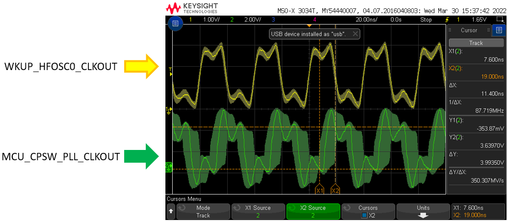
As shown above, the output of the PLL has a measured jitter of 10 ns, which is considered much to high. We expect a jitter of a few ps.
Our setup is following:
Part Number TMDX654IDKEVM AM65x industrial development kit (IDK)
The SoC is initialized with the C:\ti\pdk_am65xx_1_0_7\packages\ti\drv\sciclient\tools\ccsLoadDmsc\am65xx\launch.js script.
All PLLs are initialized with their default values. Just in case, attaching the Gel file that is used to initialize the PLLs:
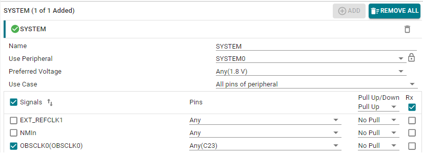
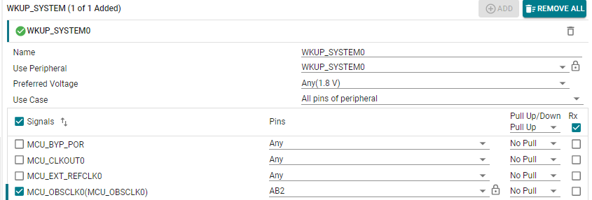
The board is initialized with the appropriate PINMUX settings:
No firmware is running.
Before measuring these signals, we check the status of the MCU_PLL1 to be sure that it’s locked in frequency (FREQLOCK) and phase(PHASELOCK) as well as reference signal is valid (TVALID):

We also took two pictures of the signals in frequency domain:
Spectrum of the WKUP_HFOSC0_CLKOUT looks as following:
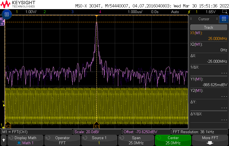
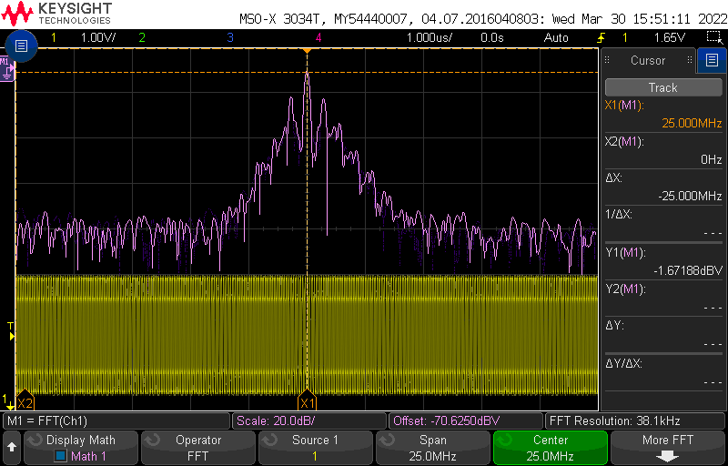
Spectrum of the MCU_CPSW_PLL_CLKOUT looks as following:
We also made sure that the Spread Spectrum Clocking function is disabled for this PLL:

Our question is:
Could you please explain why the signal MCU_CPSW_PLL_CLKOUT has so huge jitter relative to the signal WKUP_HFOSC0_CLKOUT?
Also could you please give us a hint how to eliminate or reduce this jitter?
Thank you in advance!
Kind Regards,